I cascaded three QPL9547 stages, but didn’t perform inter-stage matching. I followed the parameters in the manual, but for my first low-noise amplifier, if I remove the 100pF from the input and output, the 3.32k bias voltage is about 1.1V. If I install them, the bias voltage drops to about 0.2V. I don’t understand why this happens. The input capacitor shouldn’t block DC, so how could it affect the static bias voltage? Also, I cascaded three stages, but the gain is only about 10dB, which is far from enough.
Could you please attach a schematic, and photo/screenshot of your layout? You could try isolating each amplifier and see that you get the correct bias current. There will be a bias voltage present on the LNA input, so you do need the AC coupling. Not sure what you mean by ‘the input capacitor shouldn’t block DC’ as this is what the capacitor is for.
Connecting three amplifiers in cascade can be problematic. You have a lot of gain, especially at low frequency, so stability can be an issue. You need to ensure there is no coupling around the supply or bias lines, and there is good isolation from output to input, which may require shielding. You can get problems with blockers, as even quite small signals on the input could saturate the final LNA. When you cascade devices you do need to take into account the cascaded P1dB and IP3.
When you measure 10dB gain what is your input signal level?
What is your frequency range of interest?
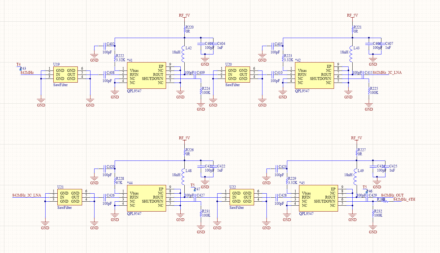
Okay, thank you for your reply.My input power is -40 dBm. For the first-stage input QPL9547, if the input capacitor is removed, the bias will be normal. However, if the input and output capacitors are added, there will be a problem with the bias voltage, and its voltage will be 0.2V.My schematic and PCB layout are shown in the picture.
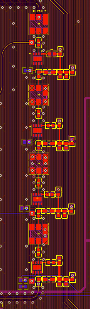
Layout looks ok but you need more ground vias under the SAW and LNA, and across the board in general.
Input of -40dBm is way too high as each QPL9547 will have nearly 25dB gain at 842MHz. So that’s 100dB gain minus loss of 4 SAW filters, say 10dB. So that gives -40dBm+100dB-10dB=+50dBm (100Watts). The Psat of the QPL9547 is about +23 or +24dBm. The last two LNAs will be getting overdriven and may be getting damaged from the very high input power.
I would start by isolating each LNA and check you get the correct bias current for each. I wouldn’t be surprised if you were getting some instability as you have very high gain and the grounding of your board does not look great. You need really good isolation between output and input of board, may need shielding. Running the LNA straight into the SAW could also give issues, as there will be a mismatch out of band. This may be ok, but could be another reason for instability.
Thank you for your reply. However, when I test them separately, the voltage across the 3.32k resistor on the first QPL9547 is only 0.9V. It has never worked properly. I also individually tested each LNA; the others are around 1.1V. Calculated, its current is 1.2mA. I want to know if this incorrect bias voltage is the reason it is not working properly. Should I evaluate the total current of the whole 9547 to check if it is working correctly? I measured 58mA under 5V when it is working, but only about 4mA when not working. However, I don’t understand why it can’t operate normally. My power supply ripple is very small. Could it be that matching issues are causing it to be unstable, leaving the bias voltage in an abnormal state?
I would suggest measuring the quiescent current (ie no RF input) into each LNA separately to check this is OK. If there is instability then the LNAs may be going into a current limiting state, which protects them from overdrive. Quite likely that you have some instability due to the high gain in the line-up, hence test the LNAs in isolation from each other first.
Okay, I’m currently measuring the current of each LNA, which is about 46 mA, and it’s the same for all three. Then, using the VNA to measure, the gain of the three QPL9547 is only -0.2 dB, and even one of them showed a very high peak earlier. I wonder if this is self-oscillation and how to eliminate it. I want to know at what current the chip enters protection, and if it does enter protection, how to release it. Thank you.
Yes there could be an oscillation. This could be due to grounding, or feedback from lack of isolation form output to input. The current limiting starts when the input power is just over 0dBm, when the parts starts to go into compression.