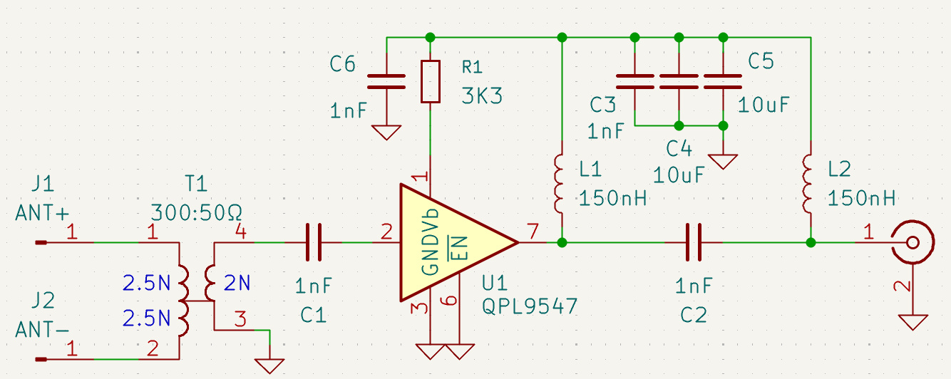
Hi, I would like to use the QPL9547 for UHF antenna amplification and also power the amp over the coax cable. The antenna’s impedance is 300Ω so a balun is used to match it to 50Ω. C2 and L2 form a “Tee” to split the DC and RF. The rest is mostly like QPL9547 eval board but with the values adjusted for UHF. I’m not sure about these values and I am curious what others think.
- Xc for C1 / C2 @ 300Mhz is 0.5Ω
- Xc for C1 / C2 @ 600Mhz is 0.25Ω
- Xl for L1 / L2 @ 300Mhz is 283Ω
- Xl for L1 / L2 @ 600Mhz is 565Ω
Do those values make sense for the QPL9547? I tried to find an inductor in that area with a self resonant frequency as high as possible. This inductor has a 1.9Ghz self resonant frequency.