Hi,
Is it a correct implementation for diff redout with QPL9547?
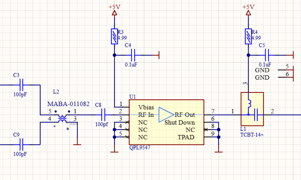
Not sure what you mean by 'redout;?
You need a series resistor of around 3K3 on the Vbias line to pin 1 of the QPL9547 to set the correct bias current. I would also add 100pF on the 5V supply on bias T pin 3. Unless you are operating wideband you could use a discrete bias T with L and C rather than the TCBT-14+. See eval board schematic and BOM in the QPL9547 datasheet.
The MABA-011082 is a 6 pin balun, so the pin out in your schematic with 4 pins does not match the MABA-011082 pin out?
1 Like
Thanks for the notes,
*readout
Yeah, MABA-007159-000000 is the correct one. In my case, it is a wideband operation.
This balun looks OK. Thanks.
BTW the bias T has very low frequency response. This opens up the low frequency gain of the LNA, which can cause stability problems. You could add a component placement across bias T pins 1 to 3. This allows addition of L or R in case you have any issues.
Yeah, TCBT-14+ is from 10 MHz to 10 GHz, the proposed 18 nH bias T in the datasheet should be from 100MHz.
Is there any lookup table for the Vbias resistor, or is 3K3 the best one? Probably it won’t affect the gain too much.
A 3K3 bias resistor with 5V supply gives typical current of 65mA. This gives best IP3 and NF. If you increase the resistor value then you can reduce bias current. This will have most impact on IP3, which will drop. Once you get below about 50mA then NF also starts to increase, and gain decrease.
1 Like