In an analog circuit I need to emulate a push button to quickly connect and disconnect a parallel RC combination over the emitter-collector connections of a transistor, in order to generate a transient pulse.
How can this be implemented ?
I tried with .step param PB 1 10Meg 10Meg but that implements only a static change.
All suggestions welcome.
Paul

@paulvo ,
Is the issue you need to generate a good pulse or how to properly switch to create a pulse.
If it’s the first, @KSKelvin provided a circuit with a V-source and a PULSE waveform specification.
If it’s the second, @KSKelvin provided a constant V-source (@1V) and used a voltage-controlled switch to generate the pulse.
Len
Hi Len and KSKelvin, the solution works perfect !
Many thanks !
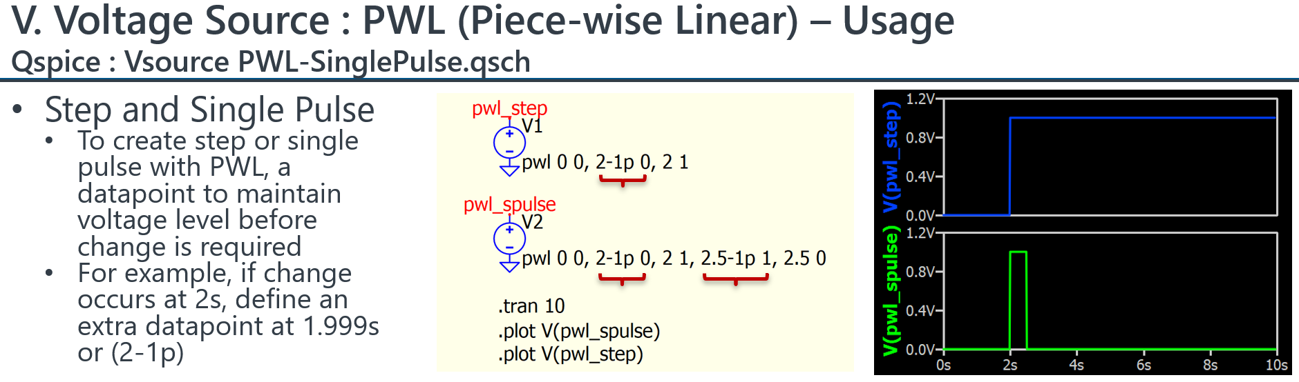
In addition, I started experimenting with Piecewise Linear in order to introduce a delay in DC voltage source.
I also found some further clarifying info from Giovanni Di Maria about “The Various Types of Power Sources” ![]()
@paulvo I am writing several guidelines for Qspice beginner. For the use of Piecewise voltage source, you can download Qspice - Device Reference Guide by KSKelvin.pdf in this Github path, and goto section V. Voltage Source, which is about p.126, I have a section showing example for that.
1 Like
Maybe too obvious, but some feedback on this topic for newbees as myself
- I found the best way to emulate a power-on switch with a 1 second delay is to use a PWL voltage source like PWL 1 0 1.2 5 as control signal for the voltage controlled switch in series with the independent voltage source with a fixed DC voltage. This will keep the DC voltage supply to the circuit steady on, after the initial switch-on delay…
- For a push-button with a delay of 2 seconds, I used a PULSE voltage source like PULSE 0 1 2 0 0 0.5 100 as control signal for the voltage controlled switch.
@KSKelvin: your Qspice - Device Reference Guide by KSKelvin.pdf is a fantastic piece of hard work ! My sincere congratulations and respect! This is now on top of my Qspice documentation.
I encourage all newbees interested in the voltage controlled switch to experiment with the positive and negative hysteresis on p.120 of KSKelvin’s Device Reference Guide.
Paul