I am currently using the DWM3000 and an STM32 NUCLEO-F429 board for some UWB SS-TWR measurements. I am using the ss_twr_initiator.c and ss_twr_responder.c examples for the tag and anchor, respectively.
I’m trying to calculate and compensate the RX power error that occurs in UWB communication. I see in APS011 page 11 that i can be calculated by friis path loss formula:
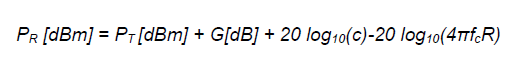
I believe I have applied that formula correctly using the following code:
  double log_term = log10(4.0*PI*6.4896e9*effectiveDistance);

  potencia = -14.3 + 1.0 + 20.0*log_c - 20.0*log_term;
  acumpot += effPot;
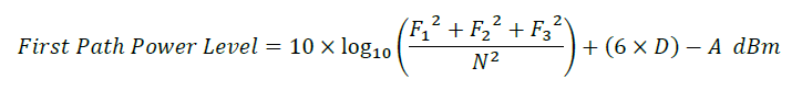
During my research, I found that the RX power can be calculated by reading specific registers and applying the values to the following function:
static dwt_rxdiag_t diagnostics;
static float F1;
static float F2;
static float F3;
uint8_t DGC_DECISION_BUFF[4];
uint8_t DGC_DECISION;
uint16_t N;


F1 = (float)diagnostics.ipatovF1/4.0f;
F2 = (float)diagnostics.ipatovF2/4.0f;
F3 = (float)diagnostics.ipatovF3/4.0f;

N = diagnostics.ipatovAccumCount;


dwt_readfromdevice(0x03, 0x60, 4, DGC_DECISION_BUFF);
DGC_DECISION = (DGC_DECISION_BUFF[3]>>4) & 0b0111;

pwr_diag = 10*log10((F1*F1 + F2*F2 + F3*F3)/(N*N)) + 6*DGC_DECISION - 121.7;
However, the results do not match the theory. In my case, at 5 meters, the expected value was -77 dBm, but I obtained the following values (each of these values is the mean of 16 mesurements):
5.2210	0.0397	-76.35	-65.12
5.2092	0.0381	-76.33	-60.45
5.2104	0.0306	-76.33	-63.97
5.2081	0.0387	-76.32	-64.22
5.2174	0.0251	-76.35	-58.74
The meaning off this values is, respectively:
- Measure distance
- Standard deviation
- Friis fromula RX power
- Diagnostics RX Power.
The actual distance is 5 meters, that error of about 20 cm i assume is due to antenna delay and RX power-related delay.
Could someone explain if I am making any mistakes in the calculations, or suggest why I might be getting such a large error?