Problems with a simple example

So i tried to implement a very simple example.
I have two esp32 Wrover modules with the DW3000.
One of them send a message every 50ms, in the payload is the tx_timestamp of its local clock.
The other one is receiving the message and calculates the rx_timestamp of the local clock, POA and clock-offset.

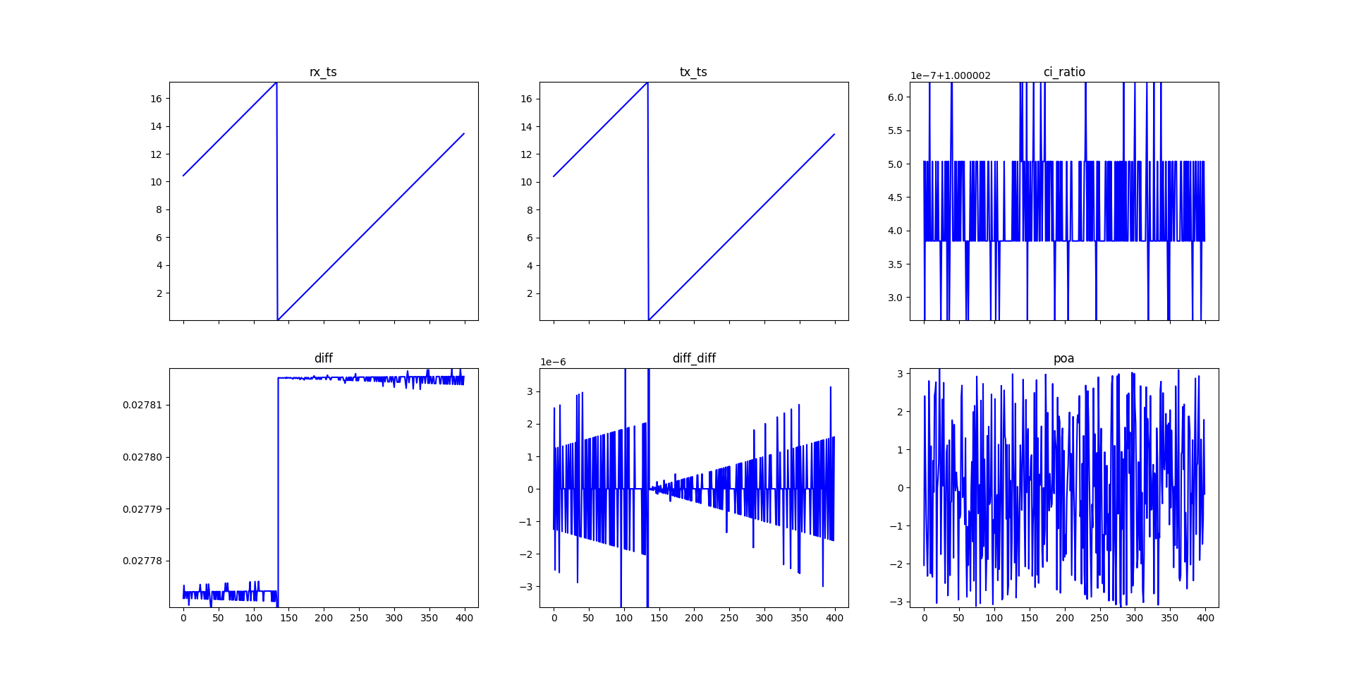
During the whole time i am not moving the boards. So in my understanding the POA and the diff (between rs_ts and tx_ts) should stay constant.

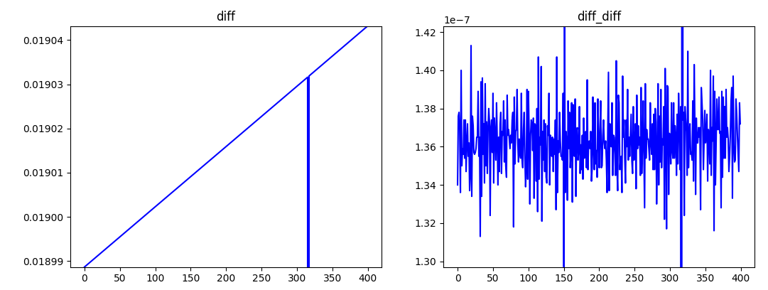
But as you can see in the image, it does not stay the same. The time difference is increasing by about 40us everytime the clocks resets.
And even between the resets, the value is fluctuating in the ns area (diff_diff is the difference of from one diff to the next, so the 1. Derivative)

And i don’t even know how i should describe the POA


I am not sure if I am doing everything correctly, or if i have a logical flaw somewhere, as i am new to this thematic, so any help would be appreciated.

I am calculating the difference like this:

#define DWT_TIME_UNITS (1.0 / 63.8976e9)
uint64_t rx_ts = get_rx_timestamp_u64();
//uint64_t tx_ts read from the received message
float clockOffsetRatio = ((float)dwt_readclockoffset()) / (uint32_t)(1 << 26);
double diff = (((double)rx_ts - ((double)tx_ts*(1-clockOffsetRatio)))*DWT_TIME_UNITS);

And the POA:

float poa_uint16_to_radian(uint16_t poa_uint16)
{
    /*
    Convert a 14-bit signed POA value (stored in uint16) to radians.
    POA format: signed 14-bit fixed-point (rad × 2^11)

    Parameters:
        poa_uint16 (int): Raw POA value (0–16383 range assumed)

    Returns:
        float: Phase in radians (range: -π to +π)
    */

	uint16_t poa_14bit = 0;
	int16_t poa_signed = 0;
	float phase_rad = 0;

    // 1. Extract 14-bit value
    poa_14bit = poa_uint16 & 0x3FFF;

    // 2. Convert to signed 14-bit integer
    if (poa_14bit >= 8192){
        poa_signed = poa_14bit - 16384;  // Two's complement for negative values
	}
    else{
        poa_signed = poa_14bit;
	}

    // 3. Convert fixed-point value to radians
    phase_rad = poa_signed / 2048.0;  // Since value is in rad × 2^11

    return phase_rad;
}

dwt_readdiagnostics(&rx_diag);
uint16_t poa = rx_diag.ipatovPOA;
float radians = poa_uint16_to_radian(poa);

Thanks
Emil

Hi Emil,

Looking at your setup and the issues you’re describing, there are several factors that could be causing the drift and fluctuations you’re observing. Let me break down the potential problems and solutions:

Clock Drift Analysis

The 40”s increase per clock reset is a bit of a clue. This suggests systematic clock drift between your two ESP32 modules. Even though you’re applying clock offset correction, there are several issues with your current approach:

1. Clock Offset Correction Issues

Your current calculation:

double diff = (((double)rx_ts - ((double)tx_ts*(1-clockOffsetRatio)))*DWT_TIME_UNITS);

Has a potential issue. You should apply the clock offset correction to the entire time difference, not just the TX timestamp. Try this instead:

double raw_diff = ((double)rx_ts - (double)tx_ts) * DWT_TIME_UNITS;
double corrected_diff = raw_diff * (1.0 - clockOffsetRatio);

2. Clock Offset Update Frequency

The dwt_readclockoffset() value changes over time. You should read it for each received packet, not just once. Also, consider that clock offset correction is most effective when applied over shorter time intervals.

3. Temperature Compensation

Crystal oscillators drift with temperature. Even small temperature changes can cause significant timing drift. Consider:

  • Adding temperature monitoring
  • Implementing temperature compensation
  • Ensuring both modules experience similar thermal conditions

POA Issues

The erratic POA behaviour you’re seeing could be due to:

1. Multipath Effects

Even with stationary modules, small environmental changes can cause multipath:

  • People walking nearby
  • Air currents
  • Humidity changes
  • Small vibrations

2. POA Calculation Verification

Your POA conversion looks correct, but verify the diagnostic data is all good:

dwt_readdiagnostics(&rx_diag);
// Check if diagnostics are valid
if (rx_diag.ipatovPOA != 0xFFFF) {  // Check for invalid readings
    uint16_t poa = rx_diag.ipatovPOA;
    float radians = poa_uint16_to_radian(poa);
}

The 40”s systematic drift suggests your clock correction isn’t fully compensating for the crystal differences. The nanosecond-level fluctuations are likely due to processing delays, interrupt jitter, and environmental factors.

The key issues to address are:

  • Clock offset correction method - apply to the entire time difference
  • Temperature effects - crystals drift with temperature changes
  • Environmental multipath - even small changes affect POA

Would you like me to elaborate on any of these points?

Best regards,
Oz

1 Like

thank you very much, I corrected the offset correction, but it still does not look quite right:

I already read the clock offset for each packet and waited for the CIA-done flag
And if I go faster than about 10ms intervall, I don’t receive any packages

As both boards are about 1.5m apart on my desk, the boards should have the same condition.

Multipath could be a problem, but i thought the boards compensate for this by finding the first path?

And could you maybe explain the clock offset correction more? because in the example, the correction is only applied to the timestamps of the distant device

Hi Emil,

Looking at your before/after plots, there’s been significant improvement, which is good to see. Let me break down what I see:

Much Better Clock Correction:

  • The systematic drift has been dramatically reduced - the “diff” plot now shows a much flatter trend
  • The scale has improved from ~0.02778-0.02781 range to ~0.01899-0.01904 range, indicating better baseline correction
  • Your clock offset correction is clearly working much better now

Significantly Improved Stability:

  • The diff_diff plot shows much tighter variation (1.30-1.42 × 10⁻⁷ vs 0 to 3 × 10⁻⁶)
  • This represents about a 10x improvement in measurement stability

Remaining Minor Issues to Address

Still Some Systematic Drift:

  • There’s still a slight upward trend in the “diff” plot, though much smaller than before
  • This suggests the clock offset correction isn’t 100% perfect yet, but you’re very close

Residual Noise:

  • The diff_diff still shows noise, but at a much more reasonable level
  • This is likely due to processing jitter and environmental factors

My Recommendations

1. Fine-tune the Clock Offset Correction

The remaining drift suggests you might need to adjust the correction factor slightly:

// Try small adjustments to the correction factor
double corrected_diff = raw_diff_seconds / (1.0 + clockOffsetRatio * 1.02); // Try 1.02 or 0.98

2. Add Moving Average Filter

This can sometimes help if your measurements are “jumpy”. To reduce the remaining noise:

#define FILTER_SIZE 5
static double diff_buffer[FILTER_SIZE];
static int filter_index = 0;

double filter_diff(double new_diff) {
    diff_buffer[filter_index] = new_diff;
    filter_index = (filter_index + 1) % FILTER_SIZE;
    
    double sum = 0;
    for (int i = 0; i < FILTER_SIZE; i++) {
        sum += diff_buffer[i];
    }
    return sum / FILTER_SIZE;
}

Clock Offset Correction

The clock offset represents how much your local receiver clock differs from the remote transmitter clock. When you read dwt_readclockoffset() on the receiver, it tells you:

“My local clock is running X ppm faster/slower than the remote device’s clock”

The Physics Behind It

When the remote device sends a timestamp (say, tx_ts = 1000), that timestamp is in remote device time. But when you receive it and measure rx_ts, that’s in your local time.

If your local clock runs fast:

  • Your rx_ts values increase faster than they should
  • The remote tx_ts values (in remote time) appear “slow” relative to your fast local clock
  • You need to “speed up” the remote timestamps to match your time base

Correct Application

// Method 1: Adjust the remote timestamp to your local timebase
double corrected_tx_ts = (double)tx_ts * (1.0 + clockOffsetRatio * 1.02);
double diff = ((double)rx_ts - corrected_tx_ts) * DWT_TIME_UNITS;

// Method 2: Adjust your local timestamp to the remote timebase  
double corrected_rx_ts = (double)rx_ts / (1.0 + clockOffsetRatio);
double diff = (corrected_rx_ts - (double)tx_ts) * DWT_TIME_UNITS;

Both methods are mathematically equivalent, but method 1 (adjusting the remote timestamp) is more common because:

  • You’re bringing the remote time into your local reference frame
  • It matches how the DW3000 examples typically do it
  • It’s conceptually simpler: “adjust the foreign timestamp to my timebase”

Why not apply to the time difference?

Applying correction to the entire time difference can introduce errors because you’re mixing two different time bases in the calculation before correcting.

The key point: timestamps must be in the same timebase before you can meaningfully subtract them.

I’d say overall you’re on the right track here. You’ve successfully implemented the main clock offset correction and achieved about an order of magnitude improvement in stability. The remaining issues are much smaller and can likely be fine-tuned with minor adjustments. UWB is inherently a bit wobbly, so you may have to play around a bit to get a good output.

Next Steps

  1. Try the small correction factor adjustments (1.02 or 0.98 multiplier)
  2. Implement a simple moving average filter
  3. Monitor temperature if thermal drift is suspected (it seems unlikely based on both boards being on your desk)

I must say that I’m fairly new to this technology too (I’ve only been using it constantly for about 2 months now) so everything I’ve told you there is from my experience. I’m sure one of the staff members (or AndyA) might be able to help you a little better.

Oz

now you write I should apply the offset correction only to the remote clock? before you wrote I should apply it to the whole difference, so whats correct now?
and before you wrote 1-clock offset ratio, now its 1+?
Could you add one of the staff members?

Generally speaking, the best people on this forum for this sort of thing are @AndyA or @akash.

There are a few ways to do the clock offset as far as I know, I got myself mixed up there, apologies. I’m currently working on something fairly similar so I got confused.

You might want to try something like this to try and fine-tune everything a bit better:

// Fine-tuning options:
double corrected_diff = raw_diff * (1.0 - clockOffsetRatio * 1.02);  // Slightly more correction
double corrected_diff = raw_diff * (1.0 - clockOffsetRatio * 0.98);  // Slightly less correction

I’d try that for a few different values and then see how it responds.

The difference in the clock values is going to increase by the difference in the clock rates multiplied by the total time between the messages.

The clock rate you measure is the difference in rates so if the transmitter is sending every t clocks you would expect the receiver to receive the message every t*(1+clock difference) clocks.

However the clock difference is constantly changing, you want to correct for the average clock difference over the entire time period. So I’d use the average of the clock difference between this packet and the previous one, that will give a more realistic average for the. So the expected difference in receive time becomes t * (1 + (clock diff this packet + clock diff prev packet)/2)

This does assume the rate of change of clock difference is constant over the time period. It won’t be but for a short enough update period it’ll be close enough.

While temperature correction is always good this is mostly going to impact the clock rates and so is already being taken into account by your clock rate corrections.

edit - To answer the question whether it’s + or - on the correction depends on which time you are correcting and which end of the link you are measuring the difference. If the correction to the receiver time is t*(1+something) then the correction to the transmitter time will be t*(1 - the same something).
To be honest I never can remember which way around it is. I tried both ways in my code, figured out which was correct and then haven’t touched that bit of code since.

1 Like

Ok thanks for the explanation.

My t is not the interval between sending packets, but the absolute timestamp of the board. Can i still apply the clock diff?

So for example:
Transmitter sends packet at tx_ts=5s
Receiver receives packet at rx_ts=1s
clock diff = 0.01 (100ppm)
tx_ts*(1+0.01) = 5.05s
diff = 5.05s-1s=4.05s

Transmitter sends packet at tx_ts=5.99s
Receiver receives packet at rx_ts=2s
clock diff = 0.01 (100ppm)
tx_ts*(1+0.01) = 6.05s
diff = 6.05s-2s=4.05s

diff stays the same

So would this theoretically be possible and correct?

practically i should smooth over the clock diff and have the intervall way shorter.
Do you have a rule of thumb what a short enough update period is?

And regarding the POA, is it really normal, that it fluctuates this much?

This paper explains what you see very well.
https://dl.acm.org/doi/10.1145/3659602

You don’t want to apply the clock error to the absolute timestamp, that would imply that the absolute error increases slowly over time then jumps back to zero. You want to apply the clock difference to the period between updates, that’s how long your clocks have had to drift apart.
I think the logic you want is this:

Transmitter sends packet at tx_ts(t0)=5s
Receiver receives packet at rx_ts(t0)=1s
diff(t0) = 0.01

Difference in timestamps is 4. (first packet so setting a baseline)

Transmitter sends packet at tx_ts(t1)=5.99s
Receiver receives packet at rx_ts(t1)=2s
diff(t1) = 0.01

Average diff over the period = (diff(t0) + diff(t1))/2 = 0.01

corrected difference at t1 = ( tx_ts(t1) - rx_ts(t1) ) * (1+Average diff over the period)

Or to look at it a different way
Increase in tx_ts = tx_ts(t1) - tx_ts(t0)
Corrected increase in tx_ts = Increase in tx_ts * Average diff over the period
Expected increase in rx_ts = Corrected increase in tx_ts
Which means if the correction is working correctly
rx_ts(t1) = rx_ts(t0) + Expected increase in rx_ts

So would this theoretically be possible and correct?

The basic theory should be possible. I’ve built TDoA based systems that are in effect using this principle.

practically i should smooth over the clock diff and have the intervall way shorter.
Do you have a rule of thumb what a short enough update period is?

The shorter the better. Personally I try to keep the interval under 10 ms when possible, I think the largest I use is 20 ms. However my gut feeling would be that unless the temperature is swinging wildly you can assume a linear rate of change in drift rate over a periods of seconds without any significant impact. Similarly smoothing helps since the difference measurements aren’t perfect. As long as you don’t smooth over too long a time period.

And regarding the POA, is it really normal, that it fluctuates this much?

Can’t help you there, I don’t use any of the phase measurement features.

I actually tried to implement another paper of the same people:
https://www.researchgate.net/publication/387772183_MULoc_Towards_Millimeter-Accurate_Localization_for_Unlimited_UWB_Tags_via_Anchor_Overhearing

Which is currently not working for me, thats how I started searching the error and implementing this simple example

Aah ok, thank you very much for the information, I will try to implement it that way