Does anybody know why the LSER attribute is not supported by QSPICE?
At high switching frequencies the series inductance of capacitors (and resistors) might have a huge impact on performance, and modelling every parasitic explicitly makes the schematic complicated and hard to read.
2 Likes
For LTspice, I made the elements with parasitic parameters myself.
I did not implement Lser for capacitors because it usually caused more harm than good.
A series inductance is not a great way to model the internal inductance of a capacitor. For foil capacitors, you really need a ladder of series R & L driving a distributed capacitance, though I’ve been able to match the complex impedance within a few degrees over several decades of frequency with just two lumps.
For ceramic capacitors, modeling their internal inductance is not really meaningful without modeling the parasitics of the PCB.
Anyway, when I watch people using Lser, it only increases simulation times without actually improving the integrity of the simulation.
Your mileage will vary,
–Mike
1 Like
Thanks for the answer.
My motivation for using LSER is actually modelling package/soldering joint inductance, not the internals. As you say, that is a bit more complex. I other words I agree with you that the pcb parasitics is important.
I was just trying to get a bit closer to reality without adding extra components to the circuit, since the parasitics of a component is easy to parameterize (and hide) from the schematics.
In LTspice I made an element - a parasitic inductance. It is a small thin line. One such inductance for a round wire, automatically calculates the value of inductance by the diameter and length of the wire. Will need to do the same for the printed conductor of the board.
It’s all in your hands.
1 Like
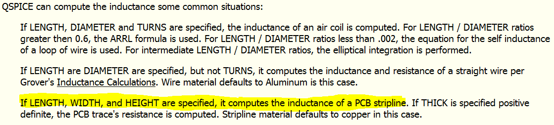
That was an excellent idea! Making a custom symbol (some sort of line) and base the model on an QSPICE inductor using the follwing parameters:
1 Like
The only thing left to do, following my example, is to make a new symbol in the form of a short, thin line. This is much easier in Qspice than in LTspice. You can also ask the Author to add such a symbol to the selectable symbols. The inductances of the printed circuit board conductors will make the circuit not look pretty.

Nice. Maybe make the symbol a thin/narrow coil symbol to make it more obvious that it’s not simply an ideal wire?
–robert
In LTspice I made the parasitic inductance as a line and the color of this line was slightly different from the color of the circuit lines. Any other symbols would detract from the circuit diagram. My idea was not to clutter the schematic.
2 Likes
Makes sense. Less clutter is more good.
–robert
A straight line is an ideal connection without any parasitics.
Replacing a physical quantity (inductance) with well-known standard symbol (inductor) with line without any visible parameters is a real mess, especially if you plan to share your circuit.
It is much better to design and use a symbol similar to inductance, such as the “single turn” shape and place inductance value.
You can make the line brown or green. You can also make the line thicker. You can also display a parameter, such as length, on the diagram. No one forbids you to do that. And don’t think your partners are stupid.
I prefer to keep my layout simple and not have anything to distract my eyes (scattered attention). You can make your inductance whatever you want - you are the master.
Your assumption is quite impudent.
Think twice before posting.