Hi all,
I am simulating resonant switching converters, such as LLC, and frequently encounter issues with achieving proper ZVS (Zero Voltage Switching) waveforms in QSPICE, even though the same circuit works well in LTspice. My typical setup uses an ideal switch model (.model SW SW (Ron=10m Roff=100Meg Vt=0.5 Vh=-0.2)) in parallel with an ideal diode (.model D D (Ron=1m Roff=100Meg Vfwd=1)), along with a parallel capacitor, such as 130pF.
I suspect the ideal switch implementation in QSPICE might differ from LTspice, which could explain the waveform discrepancies. Additionally, I have observed that PWL-based solvers often produce textbook-like waveforms for such circuits.
Is there an option in QSPICE to use an ideal device model similar to those available in PWL-based solvers, or are there recommended settings to achieve ZVS waveforms comparable to LTspice?
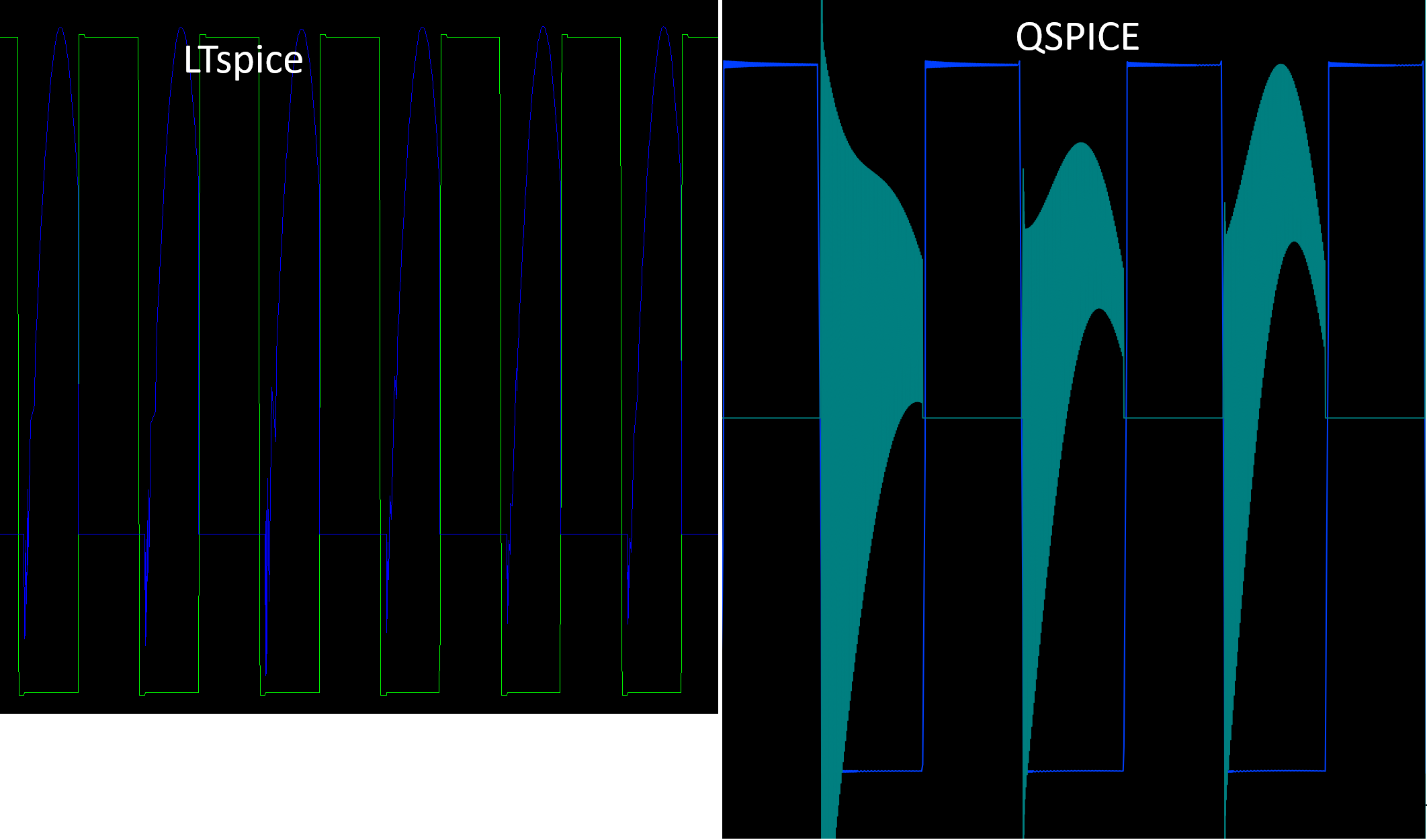
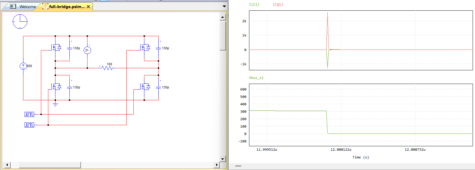
Here is an example view of ZVS plots in both QSIPCE and LTSPICE:
Can you upload the netlist which you get your waveform in LTspice? Refer to this post.
Try to give us a circuit as simple as possible that you can encounter different between simulation platform.
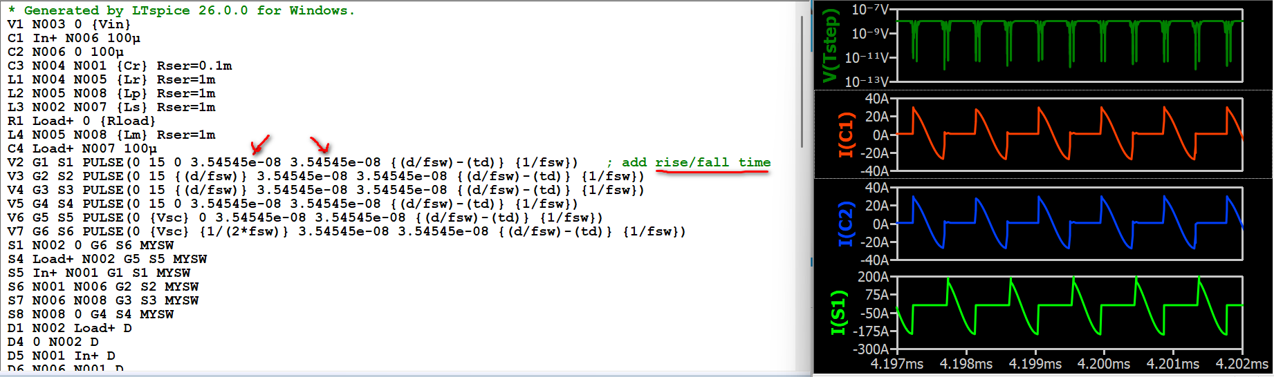
You didn’t specify the rise and fall time of the pulse, and LTspice automatically assigned a rise and fall time for you. I copied that value into the netlist.
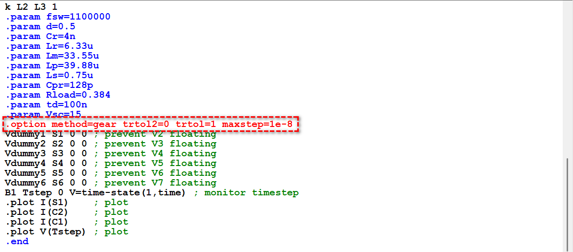
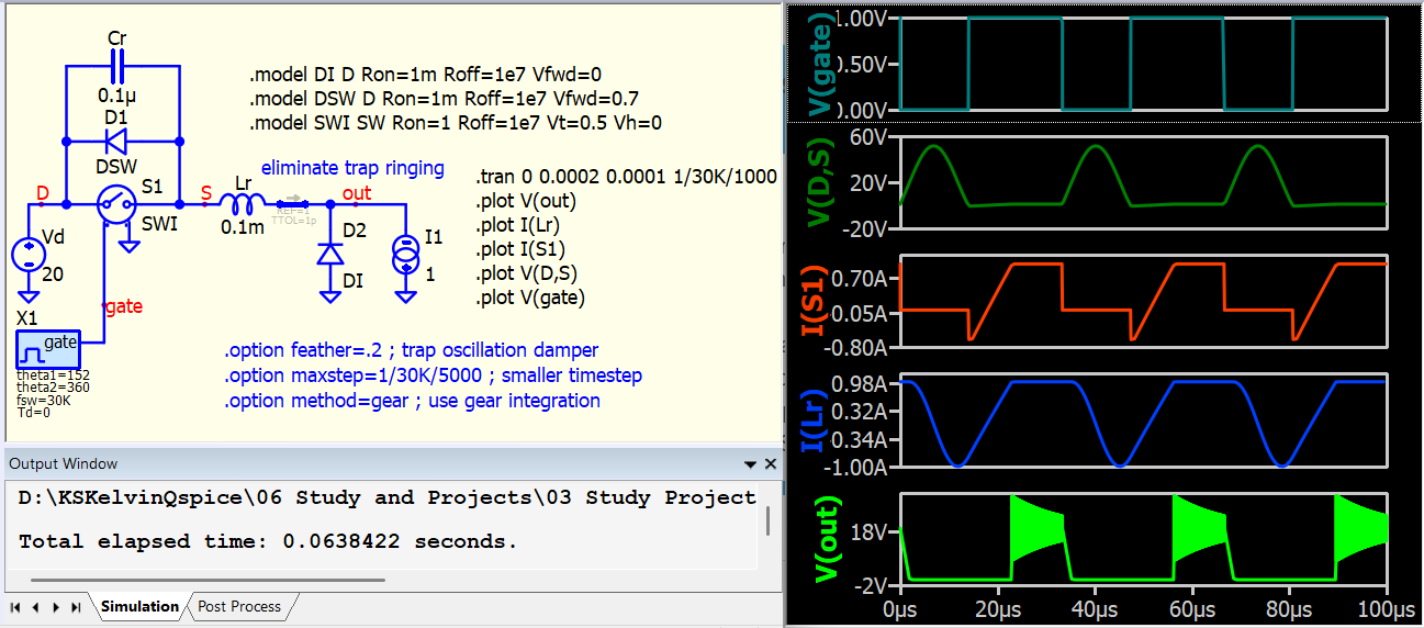
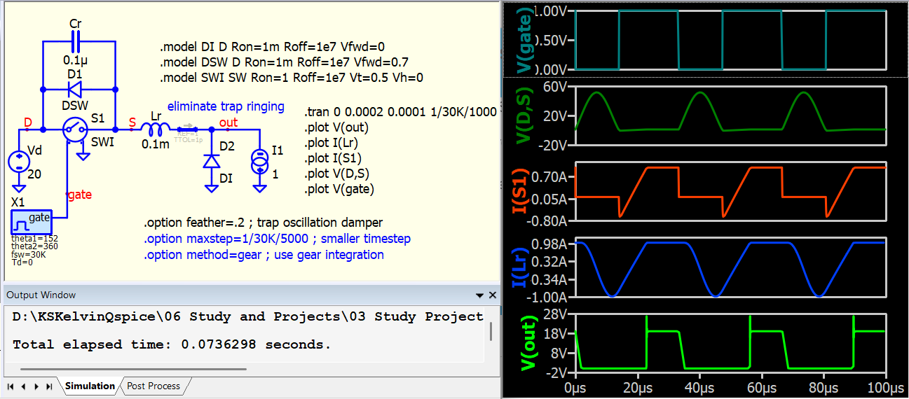
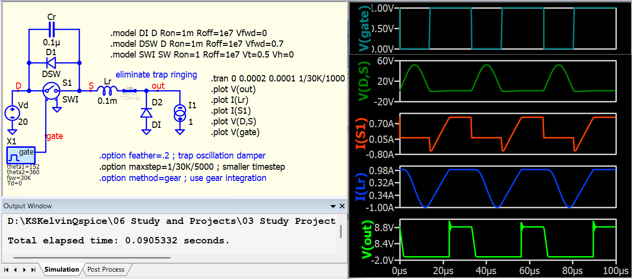
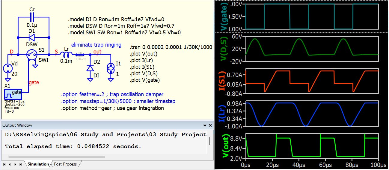
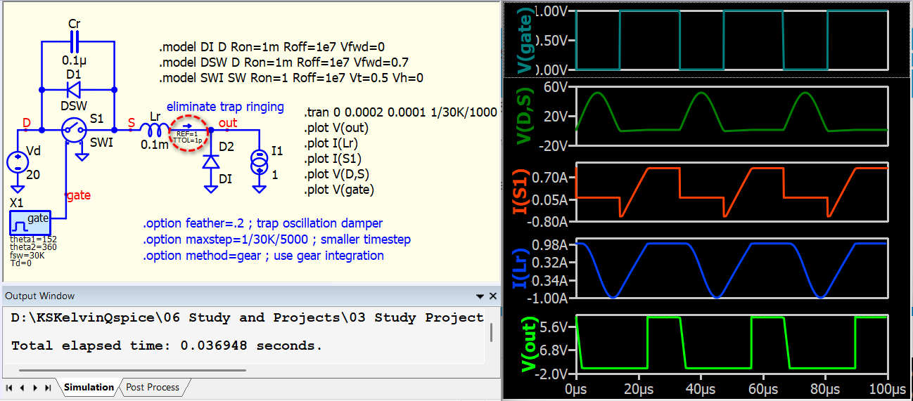
Here are some options that can help eliminate trapezoidal ringing. Well… Qspice’s timestep is quite aggressive, and in my personal experience, circuits resembling ideal simulations of zero-current or zero-voltage switching often exhibit trapezoidal ringing.
In short, what you observed is trapezoidal ringing (you can search this keyword in forum for more information), and it is related to integration method and timestep profile.
Here is Qspice netlist modified from the netlist you provided. ZVS-Qspice.cir (1.8 KB)
Thank you very much for your time and effort in providing your answer.
The netlist I sent you is very “ideal” because it uses fixed timing with pulse sources. In my actual QSPICE simulation, I am using a closed-loop converter with cascaded voltage and current control implemented in C. This is where the issue is more apparent: when the switching frequency changes to maintain CC or CV at the output, the ZVS waveform turns into this trapezoidal, ringing shape.
Since you are very experienced with SPICE and have created an excellent library and very detailed documentation, I was wondering if you know of any better “ideal” MOSFET model than what is currently available in QSPICE. By the way, thank you for all the great work you do and for making your libraries freely available. It is really appreciated.
So far, I have tried using a behavioral resistor instead of the ideal switch, and I have also tested one of the micromodels suggested here: Macromodeling ideal switches for SPICE | IEEE Journals & Magazine | IEEE Xplore. Unfortunately, none of these approaches solve the problem, and in some cases they even slow down the simulation.
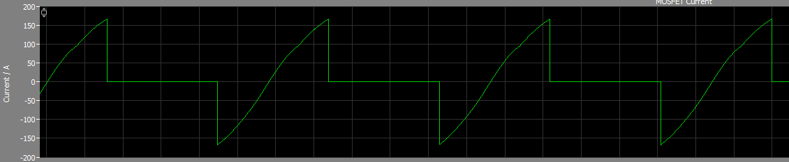
This community allows me to explore various aspects of electronics and connect with different experts. I concur that when dealing with “ideal” (or near-ideal) models in SPICE, particularly for Zero Voltage Switching (ZVS) or Zero Current Switching (ZCS), trapezoidal ringing is a common occurrence. For instance, if you modify the rise time/fall time of a pulse source in your original LTspice netlist from 0 to a finite value (e.g., 10p, not allow LTspice to assign a larger rise/fall time), you will also observe trapezoidal ringing in LTspice. In contrast, piecewise linear simulators like PSIM can provide results akin to those in textbooks for ZVS/ZCS with ideal switches.
I recommend that if you can adjust your circuit to a degree where it can be shared with the community, we may collectively determine the best approach to address it. However, this remains a highly challenging area in SPICE, particularly in Qspice, where the timestep dynamically adjusts to accelerate simulations. There is a higher likelihood of introducing trapezoidal ringing, especially in ZVS/ZCS circuits.
Here is an example of addressing trapezoidal ringing in a ZVS circuit. My understanding is that trapezoidal ringing occurs when the inductor current becomes constant (di/dt = 0), but the timestep does not align precisely with that transition point. Consequently, the integration results oscillate back and forth in the subsequent timestep until di/dt not equal 0. Therefore, I came up with an idea that utilize a subcircuit to enforce a very small timestep at the moment when the inductor current begins to transition to 1A (constant).
One thing to keep in mind is that trapezoidal ringing can be real. It can indicate that you will experience oscillations if you construct this circuit. For instance, if you introduce a 1pF capacitor into this circuit, between Lr, you will observe the oscillation.
I have attached a simpler “basic circuit” with a simplified control scheme. I will only provide the simulation and .dll files for this example.
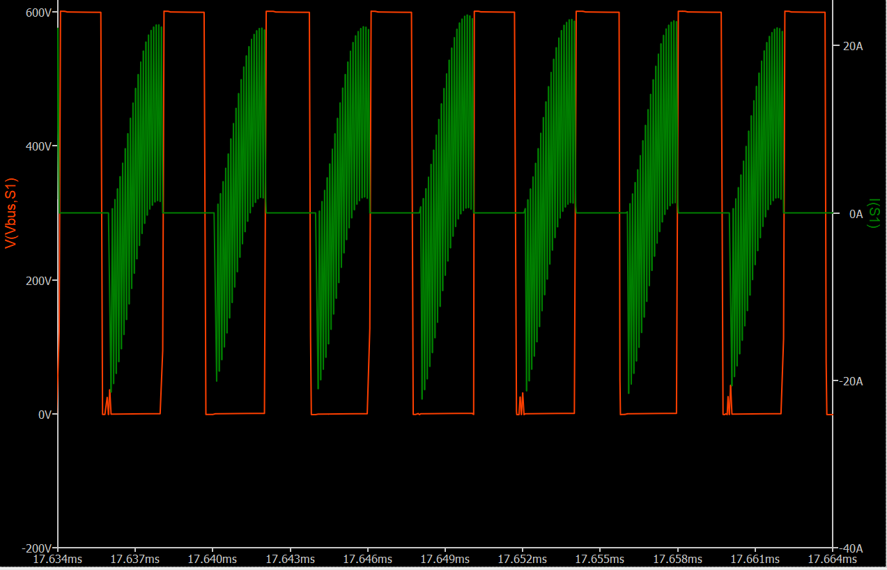
In this setup, ZVS is present, but there is still a noticeable ringing effect. The screenshot shows the simulation without control, running at a fixed frequency at resonance, which by definition should be in the ZVS region. Instructions on how to enable control and explore other cases are included as comments within the simulation file.
This option helps but also increases simulation time.
To avoid the spike before 0.5ms we we need some kind of soft-start. In closed loop this is handled. For fixed frequency you can try PWL 0 500K 0.1m 400K 0.2m 350K 0.3m 300K 0.4 270K 0.5 250K, instead of a fixed 250k FSW.
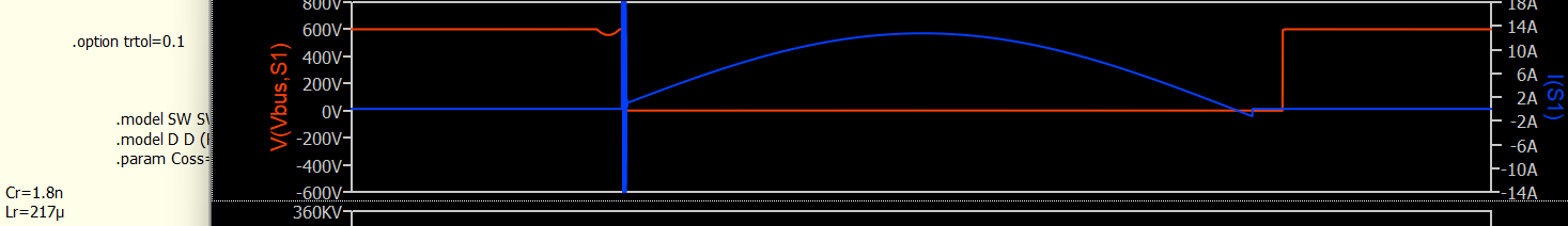
But even with trtol=0.1 I still see some oscillations.
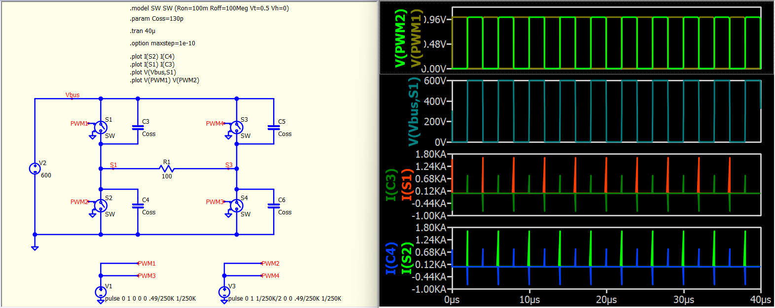
Well… sometimes, a current spike is not trapezoidal ringing but a correctly calculated result, especially during transitions. I simplified your schematic by removing as many components as possible to demonstrate how an ideal simulation can produce a significant current spike during a transition due to the high dV/dt across the capacitor. If you zoom into the waveform, it looks like a spike at one simulation timestep but it is correct calculation but not trap ringing.
This exists even in piecewise linear simulation software (refer to this example screenshot). Just consider this scenario: you have a capacitor, and suddenly an ideal switch opens or closes, causing an immediate change in voltage across this capacitor. According to the formula Ic = C dV/dt, while dV is finite, with dt -> 0, leading to Ic → infinity. This is basic electronics, where an ideal switch is employed. You may not be aware of this effect sometime in simulation, as if the simulation setup with wider timesteps to increase dt, making the effect appear less significant.
As you said this is basic electronics and I am aware of this effect. My initial post was about the trapezoidal ringing and I can say that with the trtol=0.1 I can get better results.
Now, since we are talking about ideal devices, I was wondering how we can get such a waveform using QSPICE. What kind of device can we use or what technique (if any).
Oh, I understand now. You believe the issue is related to the switch model. But trapezoidal ringing is not about the device but about the simulation timestep. That’s why all my focus is on the timestep. An ideal device is the source of trapezoidal ringing in SPICE-based simulators! The more ideal the device, the easier it is to encounter trapezoidal ringing. Integration (IDT) problem. Why? - QSPICE - Qorvo Tech Forum
An ideal switch allows an immediate voltage change across it. Any capacitor across the switch will experience infinite dV/dt and result in infinite current at the moment of transition (dt depends on simulation timestep now). However, in practice, we have inductance in series with any connection, which limits the rate of change of voltage. What you observe in SPICE generally more closely resembles the real-life situation. Please refer to this reference from Mike. Trap ringing is not an error, but telling you something can happen if you build such circuit. Apparent Kirchhoff’s law violation - QSPICE - Qorvo Tech Forum
PLECS and PSIM are linear piecewise simulators for nonlinear devices. They are designed to handle discontinuities in the I-V curve, which are present in textbooks but not in real life. SPICE, on the other hand, focuses on real-life characteristics and addresses nonlinearity. That why you need some tweak in SPICE to work with near ideal model in general.