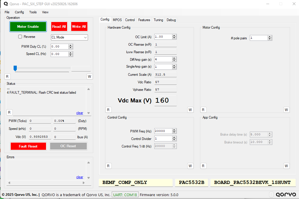
I am working with the PAC5532BEVK1 evaluation board and attempting to run the latest revision of the PAC_SIX_STEP firmware (v5.0.0). I was able to successfully build and flash the firmware; however, when I launch the GUI, I encounter the following fault message:
To troubleshoot, I looked for an installer or update for ET-UARTSWD, suspecting a possible serial communication or driver issue, but I was unable to find any relevant resources.
Has anyone encountered this issue before, or does anyone have guidance on how to resolve the Flash CRC fault or verify the ET-UARTSWD setup? Any advice would be greatly appreciated.
Thank you for bringing this to our attention. Our team is working on this bug and will provide fix very soon. In the meantime, you can use the following quick workaround to continue your PAC evaluation:
Workaround: Disable the Flash CRC test
Open firmware on IDE, and navigate to the config_app.h file.
Find line (usually line 123):
#define ENABLE_FLASH_CRC_TEST
Comment this line by adding // at the beginning.
Save the file. Rebuild firmware. Re-download firmware to PAC device
Open the GUI and connect.
Additionally, to ensure you initially setup your FW correctly. Please follow these steps.
Firmware Setup Checklist:
Selecting your board on the FW:
Go to config_board.h file. Select your EVK board from list. For your setup, choose PAC5532BEVK1
If you are using the 3-shunt configuration, select PAC5532BEVK1_3_Shunt
If your are using the 1-shunt configuration, select PAC5532BEVK2_1_Shunt
(Note: PAC5532BEVK1 is 3-shunt by default unless you have modified the board to use only single shunt operation)
Build and Flash the firmware
Open GUI
Establish UART COM Port. By going to window’s top left tab Config → COM port config → Detect → Select from available COM ports → COM Status and Target Status update → Click Write and close.
At this point, you should be ready to tune and run your BLDC motor.
We’ve identified a typo in the firmware that is causing this Flash CRC Test fault. Thanks for catching this. This will be corrected in the next firmware release.
In the meantime, here’s how you can apply the fix on your end:
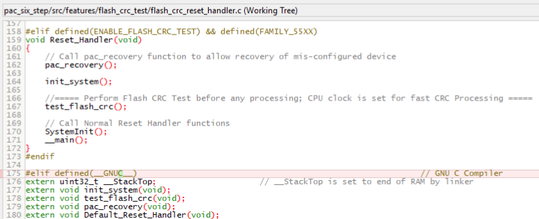
In your Six-Step project, navigate to:
src → features → flash_crc_test → flash_crc_reset_handler.c
Open the flash_crc_reset_handler.c file and go to line 175.
Ensure that the elif condition at that line matches the following:
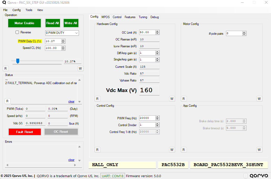
Regarding the “ADC calibration out of range” fault:
This error indicates that, during power-up, the firmware’s automatic ADC calibration detected a value outside the expected range.
To better understand your setup and identify potential causes for the ADC calibration fault
Few questions:
1. What is the VIN (input voltage) you are using for your setup? 2. Have you made any modifications to the firmware? If so, please specify which files or functions were changed.
Additionally, noticed you are using Hall Only mode, here is a quick Hall sensor checklist:
Ensure that JMP1, JMP2, and JMP3 have jumpers installed between pins 1 and 2 to enable Hall sensor functionality.
Confirm that the Hall sensor inputs are connected to the J12 connector from EVK.
If your Hall sensor hardware is open-drain, make sure to add an external pull-up resistor (e.g., 4.3 kΩ) to each Hall input.
Hi, I updated the code as you suggested and rebuilt/downloaded it. The build completes without any faults, but when I try to read all parameters, I get errors, as shown below:
Error communicating with firmware - try again
Error reading OL Zero Cross Min Speed Point
Error communicating with firmware - try again
Error reading OL Zero Cross Commutate Counts
Error communicating with firmware - try again
Error reading OL Align Time
Error communicating with firmware - try again
Error reading OL Blanking Time
Error communicating with firmware - try again
Error reading auto close loop flag
Error communicating with firmware - try again
Error reading ADC to COMP switch Speed Point
Error communicating with firmware - try again
Error reading CL Commutate Time
Error communicating with firmware - try again
Error reading CL blanking Time
Error communicating with firmware - try again
Error reading control loop PWM Duty Ramp
Error communicating with firmware - try again
Error reading Speed PI Kp
Error communicating with firmware - try again
Error reading Speed PI Ki
Error communicating with firmware - try again
Error reading Speed Min
Error communicating with firmware - try again
Error reading Speed Max
Error communicating with firmware - try again
Error reading CL Speed Ramp
Error communicating with firmware - try again
Error reading CL Mode Selection
Error communicating with firmware - try again
Error reading Reverse Flag
Error communicating with firmware - try again
Error reading CL PWM duty setpoint
Error communicating with firmware - try again
Error reading Speed setpoint
Error communicating with firmware - try again
Error reading Fix16 Var 1
Error communicating with firmware - try again
Error reading Fix16 Var 2
Error communicating with firmware - try again
Error reading Fix16 Var 3
Error communicating with firmware - try again
Error reading Uint32 Var 1
Error communicating with firmware - try again
Error reading Uint32 Var 2
Error communicating with firmware - try again
Error reading Uint32 Var 3
Error communicating with firmware - try again
Error reading Debug RTT Selection 1
Error reading motor administrative state
Error communicating with firmware - try again
The errors you are seeing are related to UART communication with the GUI and are not critical. They typically occur when the GUI is opened and factors such as power cycling the board, a loose USB cable, or Windows background processes interfering with UART communication are present.
Please note that the error log retains these messages until they are manually cleared, so it’s normal to see them persist even after the underlying issue is resolved.
The main concern is with hard faults. Are you still experiencing the ADC calibration out of range fault, or has that issue been resolved?