I have a 7-level inverter circuit using SiC MOSFET, but the output voltage is not constant. What should I do to make the output voltage stable?
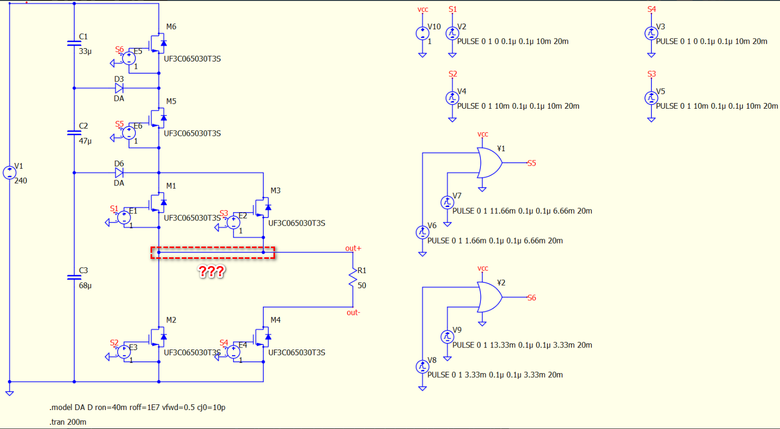
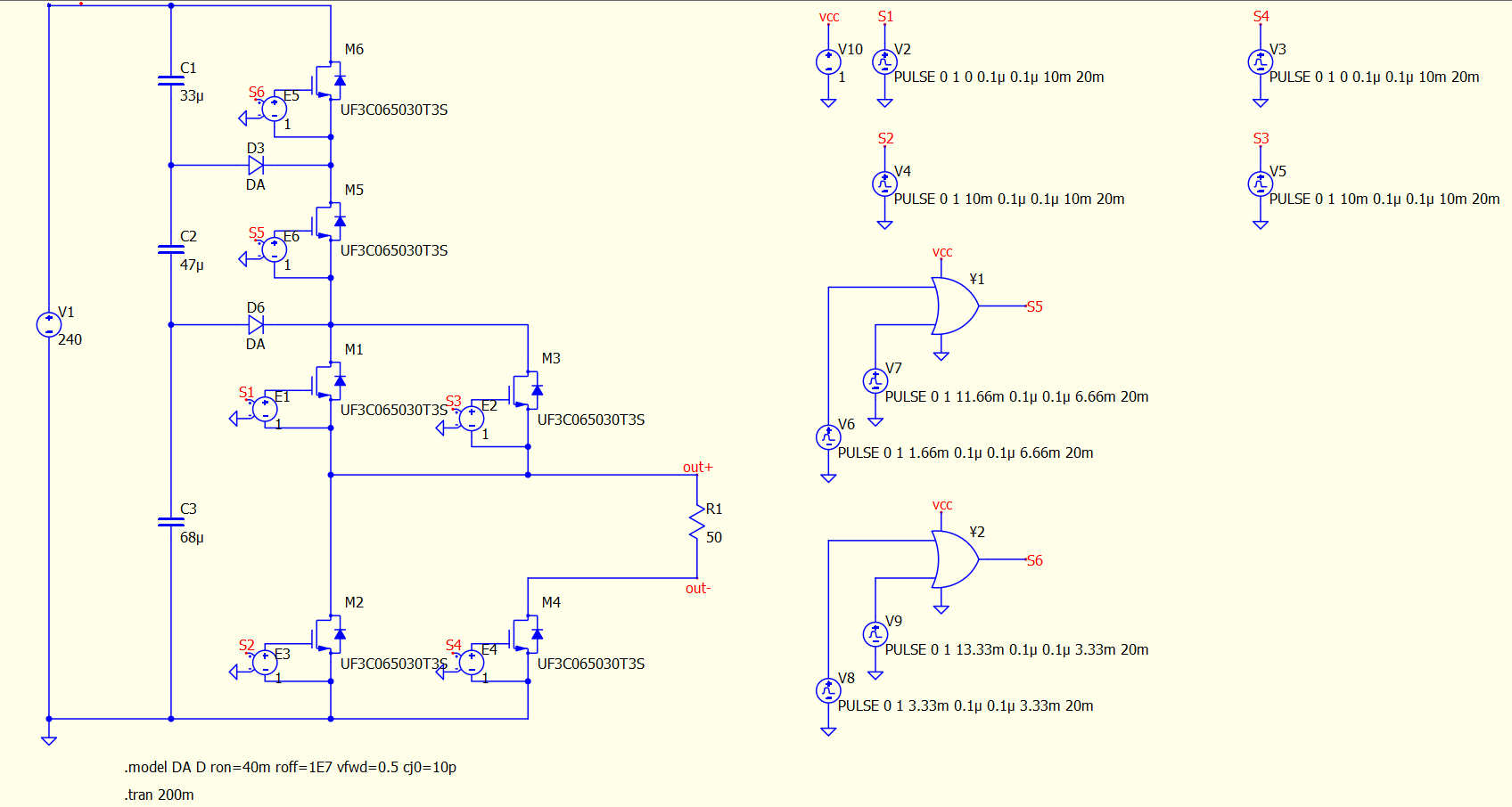
this is my circuit
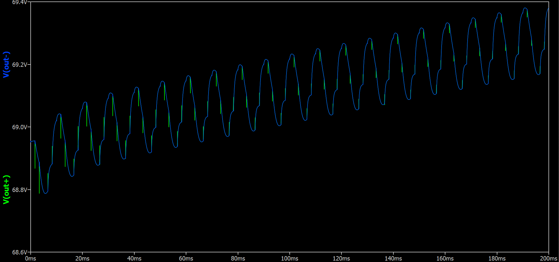
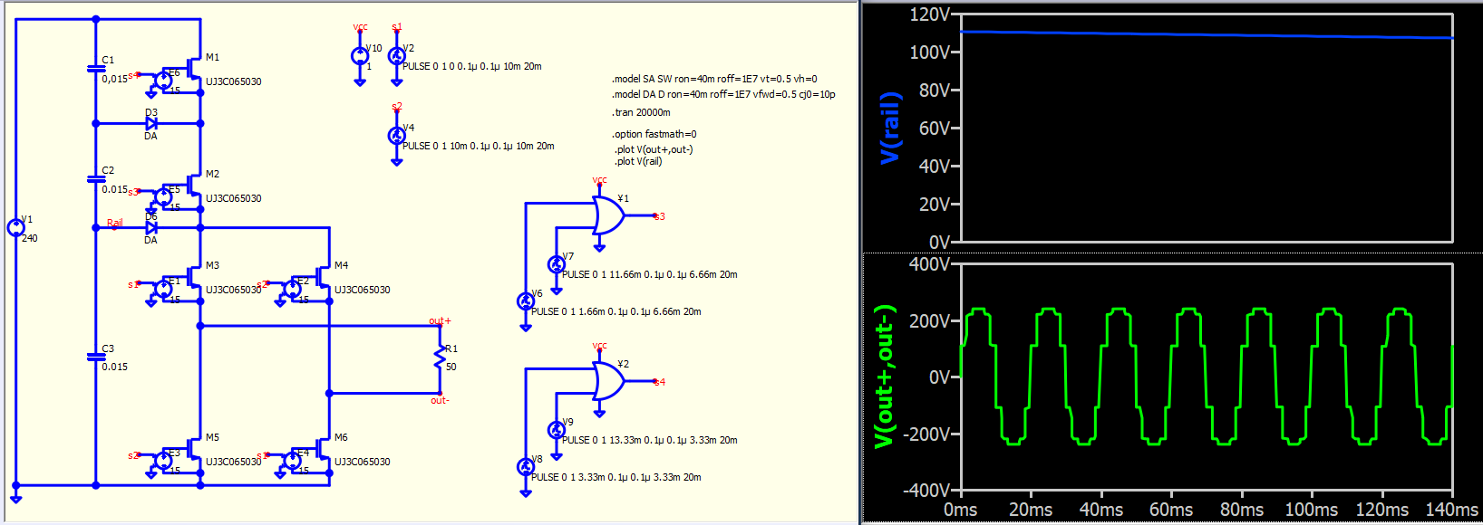
this is the output
I have a 7-level inverter circuit using SiC MOSFET, but the output voltage is not constant. What should I do to make the output voltage stable?
this is my circuit
Your invention is no good. It (the electronic circuit) is inoperable. Common capacitor nodes can only be discharged through diodes. As a result, the nodes will discharge, because there is no charge inflow!
I’ll be glad if you understand what I’m saying.
so what should i do? i have simulated on PSIM and it’s works
I have not seen your simulation in PSIM. I’ve expressed my opinion and you don’t have to listen to me. Please upload your scheme to the forum.
I believe @macsky raised a concern that there might be a wrong connection.
Generate pulse for inverter multilevel - QSPICE - Qorvo Tech Forum
It appears that your idea for the multilevel inverter involves a full-bridge configuration, with the rail voltage controlled by manipulating M5 and M6, to shift the rail and therefore, to shift output voltage level. However, as @bordodynov pointed out, how can this capacitor divider approach operate without discharging throughout the operation?
Moreover, you are driving a FET model rather than an ideal switch, and it seems that your Vgs values are 0V and 1V. How can this voltage level effectively drive the FET model to turn ON and OFF? Your previous version even seems to be better than this one.
Inverter Multilevel - QSPICE - Qorvo Tech Forum
PSIM can work? Have you added a load in PSIM like what you showed in Qspice?
I see multiple posts on this topic, and the clarification seems to have been ignored, leading to the opening of the next post. I’m somewhat losing track of how to provide you with support.
@macsky worked out a functioning simulation.
Generate pulse for inverter multilevel - QSPICE - Qorvo Tech Forum
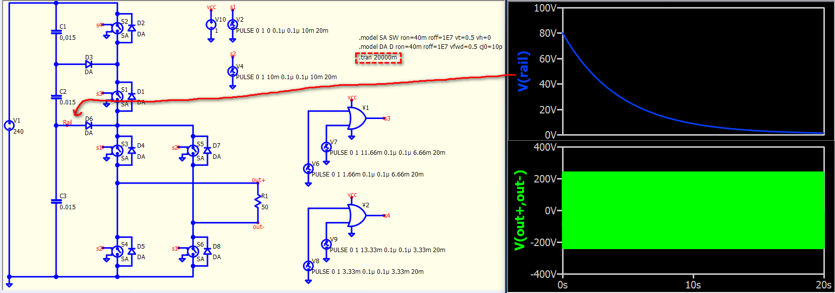
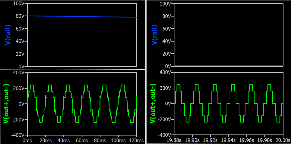
If increases simulation time to 20s, you can see C3 will completely discharged over time.
Compare the waveform at 0s and 20s, a level will gone eventually.
This is FET version, at least you have to scale the gate voltage, and need to add .option fastmath=0 for convergence. But again, rail at full bridge is still discharging over time.
forum_inverter_multilevel_7_v1-SiC.qsch (29.6 KB)
Sorry, I didn’t notice it properly before. It turns out there is indeed a wrong connection in my circuit. Thank you for your help