5M-XFO.qsch (18.2 KB)
I designed a crystal oscillator that shows to have a negative resistance at the crystal frequency but nothing happens in the time domain. I am wondering what I am doing wrong. I get the same results when I replace the crystal with a resonant tank circuit.
The schematic you uploaded is missing the library file for Q1. Managed to find a .model statement for the MMBT5179 from the Onsemi datasheet. Review if this is same as your model.
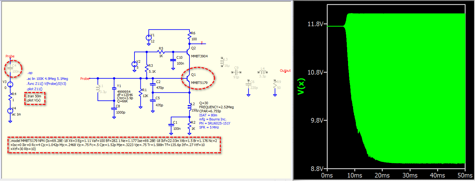
.model MMBT5179 NPN (Is=69.28E-18 Xti=3 Eg=1.11 Vaf=100 Bf=282.1 Ne=1.177 Ise=69.28E-18 Ikf=22.03m Xtb=1.5 Br=1.176 Nc=2 Isc=0 Ikr=0 Rc=4 Cjc=1.042p Mjc=.2468 Vjc=.75 Fc=.5 Cje=1.52p Mje=.3223 Vje=.75 Tr=1.588n Tf=135.6p Itf=.27 Vtf=10 Xtf=30 Rb=10)
By including this model and disabling the 100n capacitor at V(Probe) [it reactance only 318ohms @ 5MHz], an oscillation waveform can be observed. I hope this helps you move forward with your project. In the future, providing a complete, ready-to-run file will save everyone time and result in better feedback.
5M-XFO-d260502t1707.qsch (18.5 KB)
MMBT5179.qsym (780 Bytes)
MMBT5179.txt (329 Bytes)
Yes. Here is the library files. I got the values from the transistor datasheet. Mine is now working also. I must have forgot to disable the probe coupling capacitor. Thanks for your help. I am loving QSPICE simulator much more than LTSPICE. Far more intuitive and faster simulation times.
1 Like