Recently I received a AM transmitter from China, but the enclosed schematic and explanation included some errors and bad English.
So I decided to build the circuit with Qspice, to simulate various values at critical points in the schematic.
However, I could not get the oscillator to run: I only obtained DC signal lines (see first screenprint).
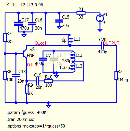
So I copied just the oscillator section into a separate schematic, which I will join as attachment.
I measured the various coils and calculated their coupling factor : measuring inductance with other side resp open (Lopen) and shorted (Lshort), and then calculate K = square root of [1 minus Lshort/Lopen].
I also tried various values for CV ranging from 400p to 40p but nothing seems to really work.
Then at last, when I concentrated on the currents flowing through L11 and L13, I finally obtained oscillations in my plots.
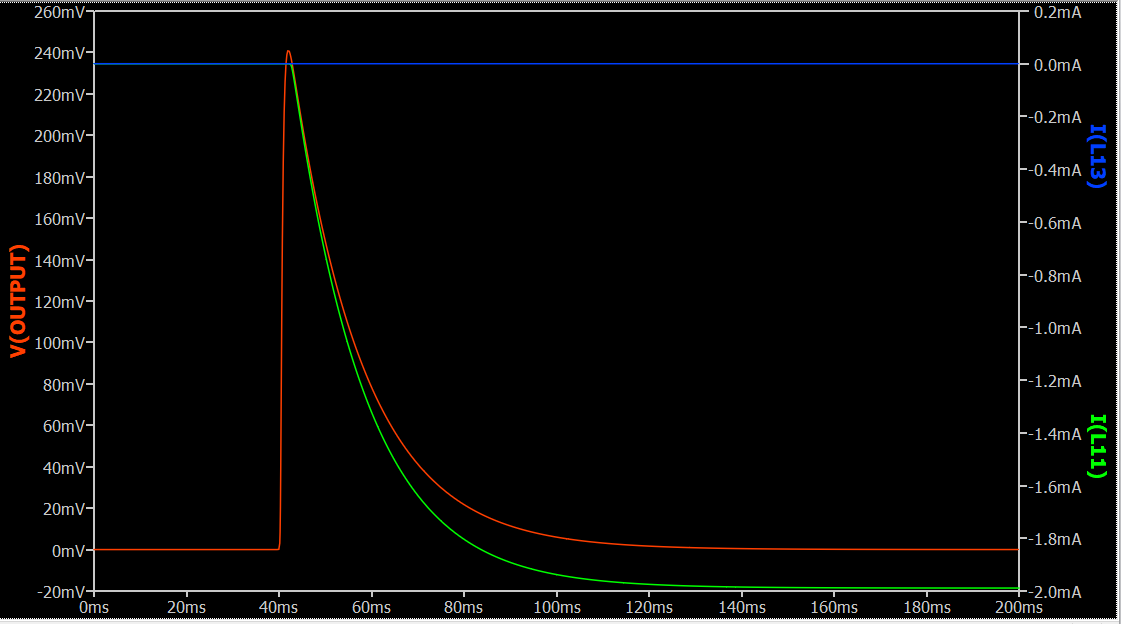
But by just modifying V3 from [PWL 0.1 0 0.11 5] into [PWL 30m 0 35m 5] the oscillations are no longer there : just a single shot to 240mV and falling back in less than 100ms.
Interestingly, after increasing to [PWL 30m 0 50m 5] for V3, the oscillations were produced again.
Also when running .tran 300m the oscillations are there, starting round about 50ms, but when
running .tran 200m only the DC lines are produced.
Actually .tran 267m is the first value to start producing the oscillations, where .tran 266m is still failing…
As I have been struggling with this for hours now, I wanted to share this with you.
Returning to the global schematic, I observed the oscillations would not be produced, even when cutting off the remainder of the circuit, and replacing with a 1 Meg resistor. Then I thought the only difference between the oscillator part circuit and the complete circuit were the power stabilizing electrolytics.
So I removed them, using the don’t stuff option.
And now the oscillations were produced again.
It looks like the power-on edge is dampened by the electrolytics, and so the oscillator has not enough trigger pulse to start oscillating.
This simulation run a high operating frequency with relatively slow time span, what you encounter may relate to simulation time step.
By reduce Truncation error overestimation factor (trtol) from default 2.5 to 1 seems help this simulation. Add this directive .options trtol=1 into your schematic and retry.
Or to give a maximum time step, for example, .options maxstep=1u
But their effect to simulation result has a bit different.
In addition, Q1 is specified a model S9018, but this model not exist in Qspice and therefore, it return Didn’t find a model for “S9018” in Output Window.
Hi Kelvin, thanks for your fast answer.
The .options trtol=1 did not help, but adding .options trtol=1 maxstep=1µ did the trick !
I could stuff the power electrolytics again.
The plot runs a lot slower now, but at least it shows the correct result.
As to the transistor, I just selected the generic ‘NPN’ again.
Just to verify, I removed the trtol=1 and indeed: the .options maxstep=1µ is sufficient to produce correct results with my oscillator circuit running at approx 400 kHz.
Good find, Kelvin !
Ah, yes, maxstep is more reliable in simulating your circuit.
It seems that you would like to add that switch S1 to delay turn on this circuit. But it may be very similar to running .tran and skip initial operating point calculation (i.e. all node voltage and current are forced to 0 unless you specify with .ic directive). Remove switch and change .tran to tran 200m uic.
Another thing you can consider is that, if your circuit needs maxstep limitation, a convenience way is to set a formula, for example
.param fguess=400k
.options maxstep=1/fguess/50
with this, you can more straightforward in ensure 50 datapoints within one frequency cycle. I am lazy in taking a calculator to calculate max step time. Just something for you to consider.