I had similar issues with SPI on my own design. It worked sometimes, bot not others. I tried all the combinations for SPI config both for DW1000 and host (I’m using Microchip PIC16F and 18F controllers) bit nothing helped. Except one thing…
I put a small 330pF ceramic capacitor to DW1000 SPIMOSI pin (pin 39 on DW1000 IC) and GND, close to the chip. It not only works for the IC itself, but same applied for me to DWM1000 module.
I’m unsure about the explanation but seems that PIC controllers have no match for impedance on SPI. Probably caused by the peripheral selection module inside them (which allows to configure in and outputs as a matrix).
I’m unsure if this would help you as I haven’t used other controllers with DW1000 yet. Also, I’m using SPI on 8MHz, but the issue was there even on slower frequencies (which even contradict my impedance theory, but in fact it’s working).
I hope you can fix your issue soon, I know how annoying it is, I spent reasonable time to fix my design.
Good luck.
@Dan Well, the issue here is not really the sampling point of the uC but merely the sampling point of the DW1000. The point is that it’s not the uC that is just receiving some bit-shifted results (which could be an issue with the sampling point), it’s the DW1000 that is sending out nothing (just 1’s) as visible on the oscilloscope.
Btw., I have to revise my complain that what is written in table 17 on page 25 of the data sheet does not match actual behavior. The point is that table 17 is referring to the Master’s point of view.
@dk1 Thanks for that input! Did you check the situation with an oscilloscope? Did you have some long wires in your design? Did you also experiment with driver strength and slew rates of your uC (if applicable)? The fact that you did it on MOSI is matching the suspicion that the issue is related with the transmission of data from the uC to the DW1000 (actually, it’s not a suspicion but a matter of fact).
I tried your patch, but it did not improve the situation. Though, 330pF are quite a lot and is increasing the slew rates to much, actually. The point is that this NXP Kinetis MCU makes for a rather short setup-time of approx. 60ns for the first bit of every transmitted byte (independent of the SPI clock rate). That is, the first bit is applied at MOSI approx. 60ns prior to the rising edge of the clock. 330pF is almost eating up this time. I also tried 68pF which is looking better on the oscilloscope, but in general the issue with the DW1000 is the same.
I still have some feeling that this 60ns setup time requirement for the first bit might be too hard for the DW1000 in that low-clock-mode. Though, the DW1000 data sheet specifies 10ns here. So 60ns would be fairly enough. But who knows…
Seems that this 60ns parameter cannot be increased. I’m thinking about implementing an hand-made bit-banging SPI implementation that would be used during that critical phase…
@Dan and @dk1 News of the day!
I found a way to extend the delay from the appearance of the first bit of each byte on MOSI to the first rising clock edge. Right now it’s approx. 260ns rather than 60ns. And guess what it does: Initialization is working smooth. So it really seems that the MISO setup time (t3) of 10ns as advertised in Table 18/B of the DW1000 data sheet is not correct.
Perhaps these 260ns can be reduced. I didn’t test yet.
For people that are using the Kinetis micro controllers (or perhaps similar Freescale/NXP controllers using the same SPI hardware):
There are so-called SPIx_CTARn registers that contain various timing settings. There is also a “PCS to SCK Delay Prescaler” and a “PCS to SCK Delay Scaler”. Both define the delay from activation of ChipSelect to the first clock edge. The firmware I’m using here resp. I based my experiments on is not using automatic ChipSelect generation for yet unknown reasons. So the ChipSelect is manually brought active and inactive. But as it turned out, the “PCS to SCK” delay does also affect the setup time of the first bit of each byte. The Kinetis SDK v1.3 I’m using here seems to provide no generic way to adjust the “PCS to SCK” delay during the standard SPI configuration. I found that these settings are hardwired in DSPI_DRV_EdmaMasterInit() in SDK/platform/drivers/src/dspi/fsl_dspi_edma_master_driver.c. There I changed the line
DSPI_HAL_SetDelay(base, userConfig->whichCtar, 0, 1, kDspiPcsToSck);
into
DSPI_HAL_SetDelay(base, userConfig->whichCtar, 0, 3, kDspiPcsToSck);
So instead of prescaler 0 and delay 1 I’m using prescaler 0 and delay 3. Perhaps a delay value of 2 is working as well…
That’s all (so far, at least…)
Thanks for the help and listening…
@dk1 Regarding your issue (although already solved with the capacitor) I really think that there was a problem with massive ringing on MOSI due to long wiring and/or too steep edges. Perhaps you should check that again.
Sorry, I’m wrong.
I made some measurements again on FPGA with SPI.
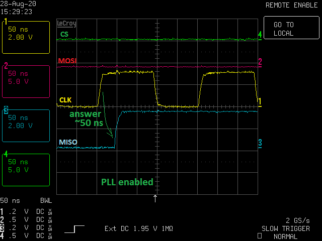
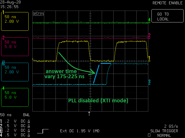
DW1000 will set new bit on MISO after CLK goes high with some delay.
Delay is ~40ns for DW PLL mode, and up to 240ns for XTI mode.
So the best way is to sample MISO line on CLK transition to high.
Tomorrow I going to test how low byte-byte delay can influence on DW1000 in PLL and XTI modes.
Test #1 Every 50 ms within 10 secons repeat the steps:
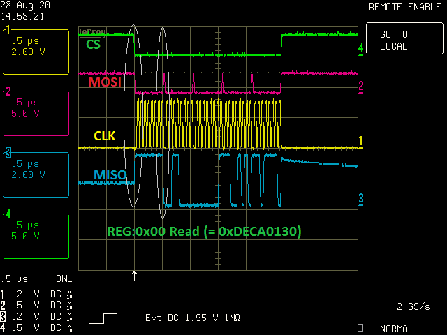
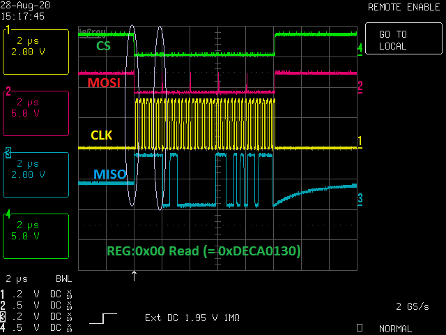
Step 1: Read Reg 0x00 and compare with 0xDECA0130
Step 2: Write 30 bytes with value from 0 to 29 to Reg 0x21:00
Step 3: Readback 30 bytes from Reg 0x21:00 and compare with data written
Set /SPI CLK to 10MHz/ b2b delay 250ns/DW to PLL mode then RUN TEST1 - Passed OK
Set /SPI CLK to 10MHz/ b2b delay 25ns/DW to PLL mode then RUN TEST1 - Passed OK
Set /SPI CLK to 3.1MHz/ b2b delay 250ns/DW to XTI mode then RUN TEST1 - Passed OK
Set /SPI CLK to 3.1MHz/ b2b delay 25ns/DW to XTI mode then RUN TEST1 - Passed OK
Looks like byte to byte delay can be as low as 25 ns at any DW mode.
@Dan Yes, usually things are implemented so that the transmitter changes the date with one edge of the clock and the receiver samples the data with the other edge of the clock.
Regarding your test: Not sure what your “byte to byte delay” is refering to. In the data sheet there is this t5 which is the time from the sampling edge of the last bit to the appearence of the first bit of the next byte. As I pointed out earlier, I believe that the diagram in figure 26 is not correct and t5 stretches from the sampling edge of the last bit to the sampling edge of the first bit of the next byte.
In case these 25ns that you achieved in tests is more or less t5, this would be surprisingly low, because the data sheet specifies 32ns resp. 205ns here. Despite the fact that you can go much faster, I would not count on that resp. let my design base on that, however. The point is that we do not know what is going on inside the DW1000 under all circumstances. My observation so far was that the DW1000 needs a setup-time of more than 60ns (right now I’m going with 260ns) in XTI mode. At least this is valid for the first bit of a byte, perhaps also only for the very first bit of the whole transaction. Only Decawave knows…
So in case you experimentally achieve byte-to-byte delays of 25ns even for the XTI mode, this rather large setup time I experienced might only be needed for the very first bit of a transaction (i.e. the read/write indicator). When even a 60ns setup time did not work in my setup, I doubt that 25ns are working for you. So probably your setup time for the very first bit is larger than 60ns.
Anyway, right now I’m happy with the situation. For my application I do not need to fight for every nanosecond.
Great news, well done!
This is a very interesting and complex issue you solved. Now you can focus on more high level things
Actually, I checked my config and I used a 33pF capacitor but in the drawings I marked it as 330pF. So thanks again for highlighting it, I fixed my documents.
@Mario2020 Hi, Mario,
Could you take an oscillogram and highlight what time are you meaning. I still want to reproduce an issue on my FPGA based test platform, it can operate with any timings with 12.5 ns resolution.
@Dan boahh… I tried to place oscilloscope screenshots here and got the message “New users cannot upload images”…
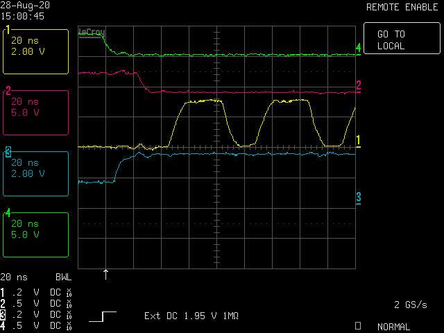
Anyway, the time I’m referring to is actually t3 of the data sheet. In my initial experiments this was 60-70ns for the first bit of a transmitted byte. These 60-70ns were independent from the SPI clock rate. The byte-to-byte delay is t5 in the data sheet, although I believe that t5 should stretch until the the first sampling edge. In my case (assuming a 1MHz clock) these were around 630ns.
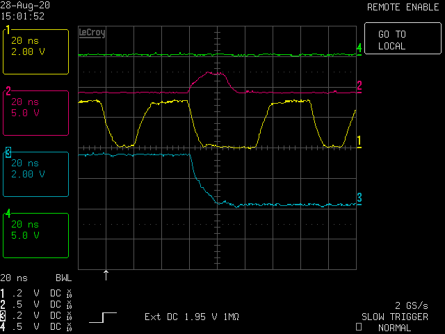
What is also visible with the Kinetis MCU: After completion of the last bit of a byte resp. the falling clock edge after bit 0 has been transmitted (refer to figure 26 of the data sheet) it is driving MOSI always high for a moment and then outputs the next valid bit with a setup time of these 60-70ns until the clock is rising again.
In addition, I found that there is maybe also a relation with the activation of the ChipSelect. Initially, the ChipSelect has been activated manually in my application. So it turned low well before transmission of the first bit (several micro seconds). In the mean time I was able to change the firmware so that the ChipSelect is getting activated automatically now. In fact, ChipSelect is becoming active together with the first bit of the first byte these 60-70ns before the first clock edge (assuming the standard settings). Now, as I reverted the design back in order to make the screen shots, I noticed that the probability of error did drop significantly. However, there was still some issue. Although the initialization did pass, my receiver did not want to receive packets. Things were ok again when I did increase the setup time for the first bit of a byte again (130ns seem to be ok as well). Actually, I’m too tired to watch more into that matter. I need to do some other things to get ahead…
To conclude: In order to reproduce the problem you should perhaps do the following things (assuming default SPI settings of the DW1000):
Activate ChipSelect some micro seconds before the transfer starts. Keep MOSI high here.
When the first bit of a byte is to be transferred and it is a zero, then drive MOSI low not more than 60ns before the rising edge of the clock.
After the falling edge of the last transfered bit of a byte, drive MOSI high immediately before starting over with the next byte. I’m seeing high-times of MOSI of approx. 25ns independent from the SPI clock setting. Of course, this merely “spike” is only visible as such when the bits transmitted before and after are 0.
That’s all I can say for now. Perhaps I can also post the screenshots in one year, when I’m not a new user any more…
@Mario2020 Hi, Mario,
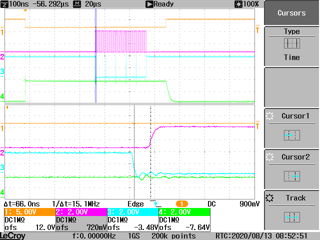
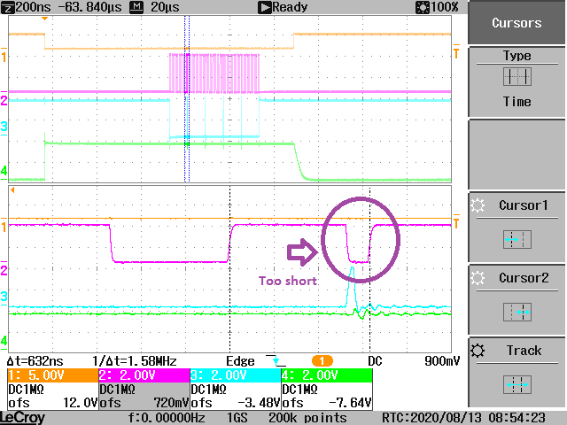
I’ve done some tests trying simulate yours signals behaviour. The results you can see below.
But your SPI CLK signal looks corrupted, it is not normal for SPI at all. I think it is the only reason incorrect behaviour of your system.
@Dan So if I understand this correctly, your finding is that the MOSI setup time is at least 25ns in PLL mode and 100ns in XTI mode? This is matching my observation that these 60ns I had initially are too short. The DW1000 data sheet specifies even shorter 10ns here.
I’m not seeing a relation with a “corrupted clock” in my setup. For sure, the slew rate is not very high in my setup, but it should be ok. The DW1000 data sheet does also not specifiy maximum rise and fall times. Right now I’m operating the DW1000 in PLL mode with a 15MHz SPI clock without any issues. Though a higher clock rate (I tested 18MHz) is bringing in first troubles. But that’s not a key thing right now and there are also hurdles like cable length and even a bit of “free air wiring”. So all in all I’m happy with the signal quality considering the circumstances.
But when your finding is that the DW1000 needs a MOSI setup time of 100ns (rather than 10ns as advertised), then this is clearly the issue and Decawave should fix this in the data sheet.
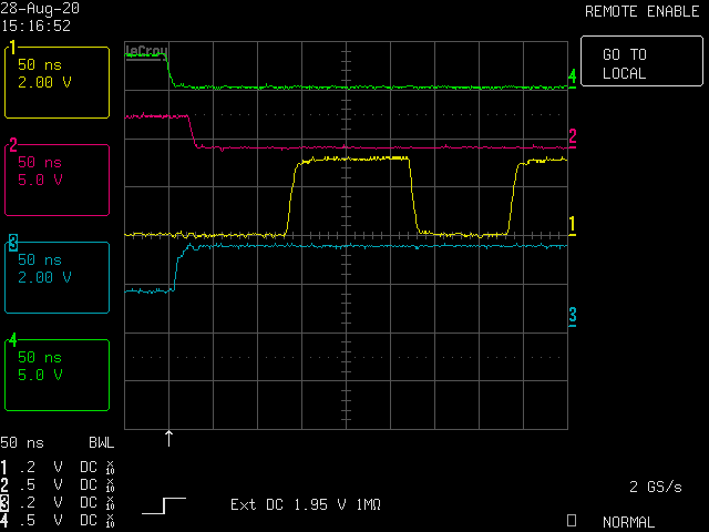
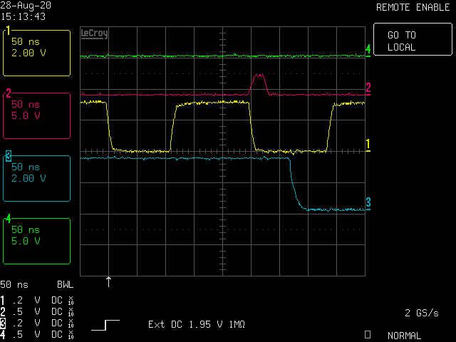
For reference for others I’m attaching my screenshots here (I’m allowed to do this now…). It is showing a non-functional read of the ID reg due to a MOSI setup time of just around 66ns.
@Dan I did write about that matter earlier. The screenshot is showing the byte-to-byte delay. In earlier attempts to fight this issue I tried to send out bytes manually one by one with plenty of time in between. Here this short low-phase of the clock was not present resp. takes micro seconds. This did not change anything, because the problem was apparently with the setup times. Though, this might be a secondary problem as well. With the micro controller’s SPI hardware (NXP Kinetis) this particular delay did also increase. So in case this is an issue too, it has been solved at the same time.