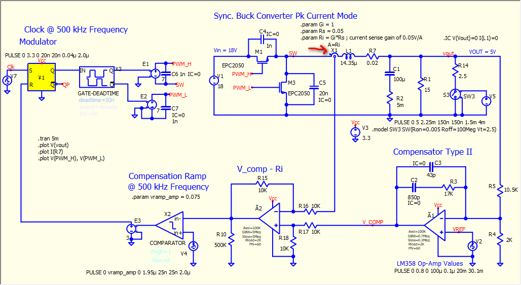
during development, say you want to calculate a gain based on existing component values. In my schematic, I have resistors R7, R15, and R16. I have tried the following:
.func Ri(R7, R15, R16) Ri{R7*R15/R16} ; does not work
.param Ri=R7 * R15 / R16 ; does not work
.display Ri
I am not able to obtain existing component values. Can you do this without having to define each existing resistor value (or cap/inductor for that matter) with .param keyword. This would seem a bit redundant since they exist on the schematic. Can’t it just recognize the component reference designators and pull their values automatically in the equation?
This is what SPICE does, you never find a SPICE based simulator with what you describe. One of the reason is that, for example, R-device, you not only have option to define it as a fixed resistor, but you can set a R with a formula, for example, R=V(ctrl)+10k, as a result, it resistance can change during simulation.
A device can have multiple instance parameters. As a result, it make sense you only read the variable you define with .param.
I just wanted to print the gain Ri for verification (i.e., Rs * Ga). I am currently attempting to run a “peak current mode buck converter” but I am not able to get it to work. I was going to replace the differential op-amp circuit that I am currently using as the current feedback amplifier with a voltage source (i.e., V = Rs * Ga * I(L1), where .param Ga = 2).
The original equation was to verify the gain of the diff op-amp itself. I wanted to print the gain to the terminal.
Here is the circuit. Can you please provide feedback as to what I am doing wrong. This is with respect to the example provided in this tutorial:
What you can do is to use a B-source and use there the formula of your calculations and read back this voltage.
For example say you have R1 and R2 and you want to get their product. You can do the following.
.param R1val=1k ← Set the value of R1 to R1val instead of typing 1k
.param R2val=2k ← Set the value of R2 to R2val instead of typing 2k
In the B-source put V=R1valR2val. You can also use a behavioral resistor and set its value to the result of this B-source, or set directly its resistance using the same expression as in the B-source (R=R1valR2val).
If I am getting it right you are trying to calculate some compensator values. The best method I have seen so far is done in Christophe Basso’s simulation models. I highly recommend you to check these simulations. It has everything you need to start learning about basic topologies.
@toms I think @qspice_newb know this method (use .param), he just doesn’t like that and ask for reading resistance directly from the name of the R-device.
If R7, R15, ... are reference designators, they do not have any value attached to them, they’re simply “nicknames” so, if your netlist looks like this: R7 node1 node2 1k, using .display R7='R7' will not work,since R7 is not a value. If, instead, you’re using .param R7=1k and then use R7 node1 node2 R7 in the netlist then R7 will be a value that happens to share the name as its reference designator, and which can be used with .display. To make it less confusing, you can use .param res7=1k and .R7 node1 node2 res7, with .display R7='res7' (whatever suits you). The name of the value is different than its actual value and is given by the expression to the right of the =. If the expression does not have actual values, there’s nothing to calculate.
Vlad
PS: To be more clear (hopefully), the netlist is made of <reference_designator> <node_name_1> <node_name_2> ... <node_name_N> <value> (or <expression> instead of <value>, or …). In the same way you can’t use the ref. des. as a value, because it’s just a label, you can’t use a node name as a value, unless you explicitly assign a value to it, e.g. .param N1=3.14 and then use R7 N1 node2 res7val (with e.g. .param res7val=1k). Here, N1 is replaced by its value during pre-processing, while node2, having no value, is treated like a label (automatically assigned, or not). I don’t wear my best english coat today but, I hope some part of the message went your way.
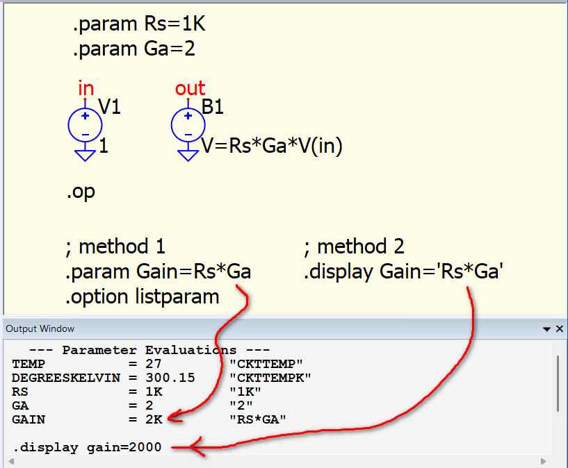
Here are two methods to return computed results. The community can only offer guidance based on Qspice’s current capabilities. If you would like to request that Qspice return a fixed component value based solely on its device name (designator), you should email Mike directly with that feature request. However, based on my understanding of how SPICE works (possibly also other experienced members), such a request may not be technically standard or feasible.
I see. You are probably not very familiar with LTspice and you have also not read the “Readme_please.pdf” file contained in the zip. Once you do it, then everything will be clear.
Also, if you try to use these models in QSPICE be aware that some of them will not work because they use A-devices. I believe there are some translators already available but @KSKelvin is the expert on this. Maybe if there is interest he can port all of these models to QSPICE and upload them to his GitHub repo.
Edit: Please have a look in his models page here. I am pretty sure he has PCM. When you see average in the name of the file it doesn’t mean he is using average current mode control, he is using the “average switch model”. I guess you some reading to do now!
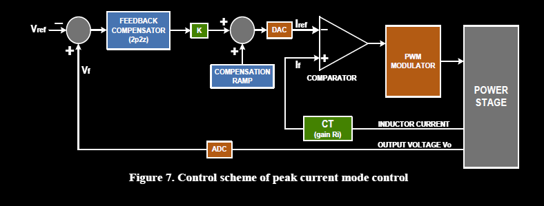
Ok, finally got it to work. Apparently I was going about it the wrong way. In the original version, I was subtracting the ramp from the measured current. Turns out I had to subtract the measured current from the compensator control voltage signal. Thereafter, subtract this result from the compensation ramp. Here is the block diagram that I used for reference:
This figure is from NXP/Freescale Semiconductor AP4716 titled: Digital Peak Current Mode Control of Buck Converter Using MC56F8257 DSC
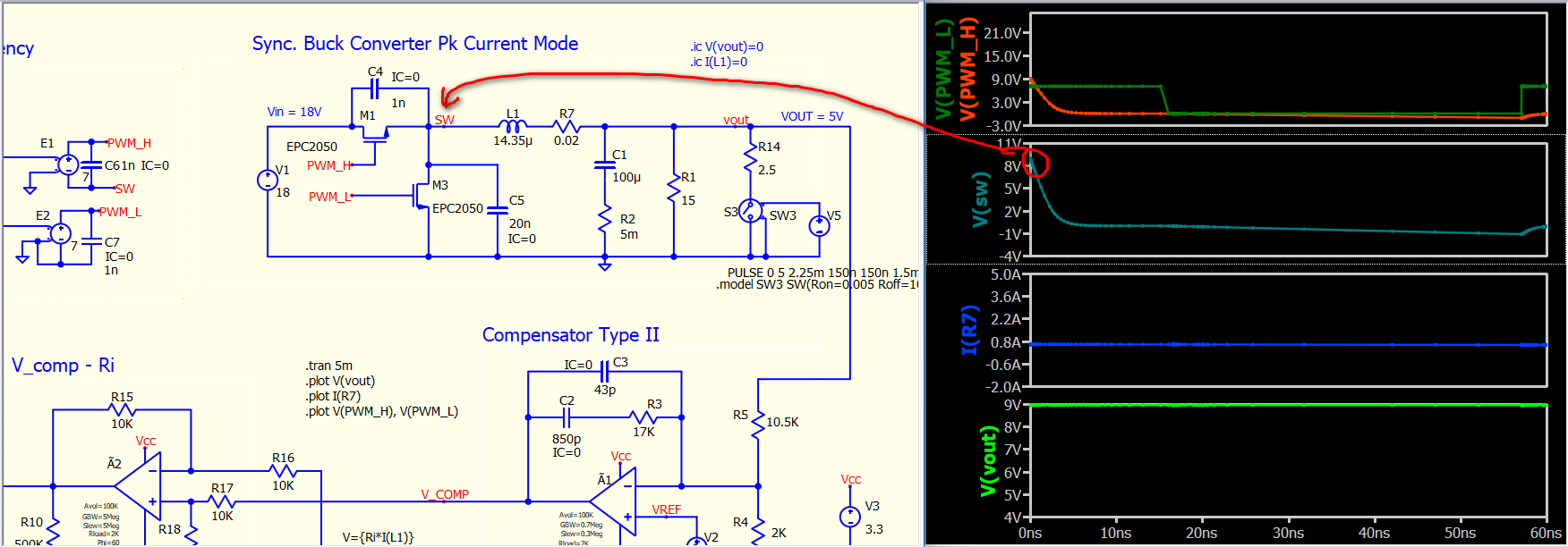
Here is the working example if anyone is interested regarding a buck converter with peak current mode (see a previous post regarding link to website where the Type II compensator values were obtained along with the theory).
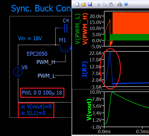
One thing that anyone new to SPICE often misses is that in a transient simulation (.tran), the solver needs to first resolve the DC solution (.op). All voltages and currents at t=0s depend on the DC solution. For power electronics circuits (switching circuits), this can be tricky. Power electronics engineers always assume all voltages and currents start from 0V/0A, but this is not the case in general.
There are multiple ways to handle startup conditions:
Power stage starts with Vin=0V: Change V1 from 18V to PWL 0 0 20u 18 so Vin ramps from 0V at t=0s.
Power stage starts with 0V/0A output: Add .ic V(vout)=0 I(L1)=0 to ensure the power stage initializes with zero output voltage and current at t=0s.
Skip DC operation point and start with incorrect dc condition: Change .tran 5m to .tran 5m UIC. While not a recommended practice, it is frequently used as because not understand what UIC actually does. (Timestep too small solved by .tran uic? - #5 by Engelhardt)