Dear Sir/ Maam
I had performed one simulation on Qspice software regarding low pass filter in order to obtain its gain plot where the circuit is T shaped circuit having 2 inductors. One inductor having value 130nH and the other one is having 220nH and in between their junction I used a capacitor having value 20pF and the source that I used is sinosoidal input where I kept offset value = 0, Amplitude of 2V and frequency is of 160 Mhz and in that simulation I had written some spice directive command and I am not sure whether it is correct or wrong. So please can you help to overcome through this problem with proper explanation and also I attached the image that I got after simulation.
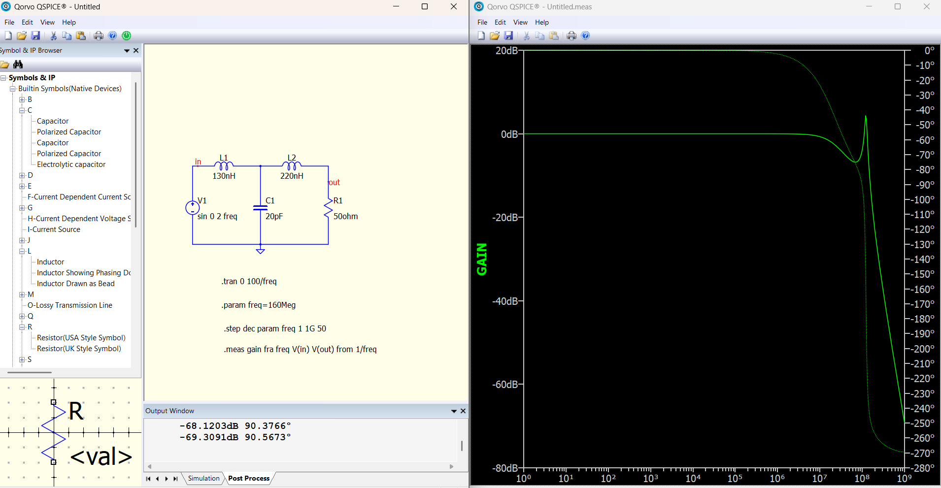
I guess you are asking why the gain is up at about 125MHz?
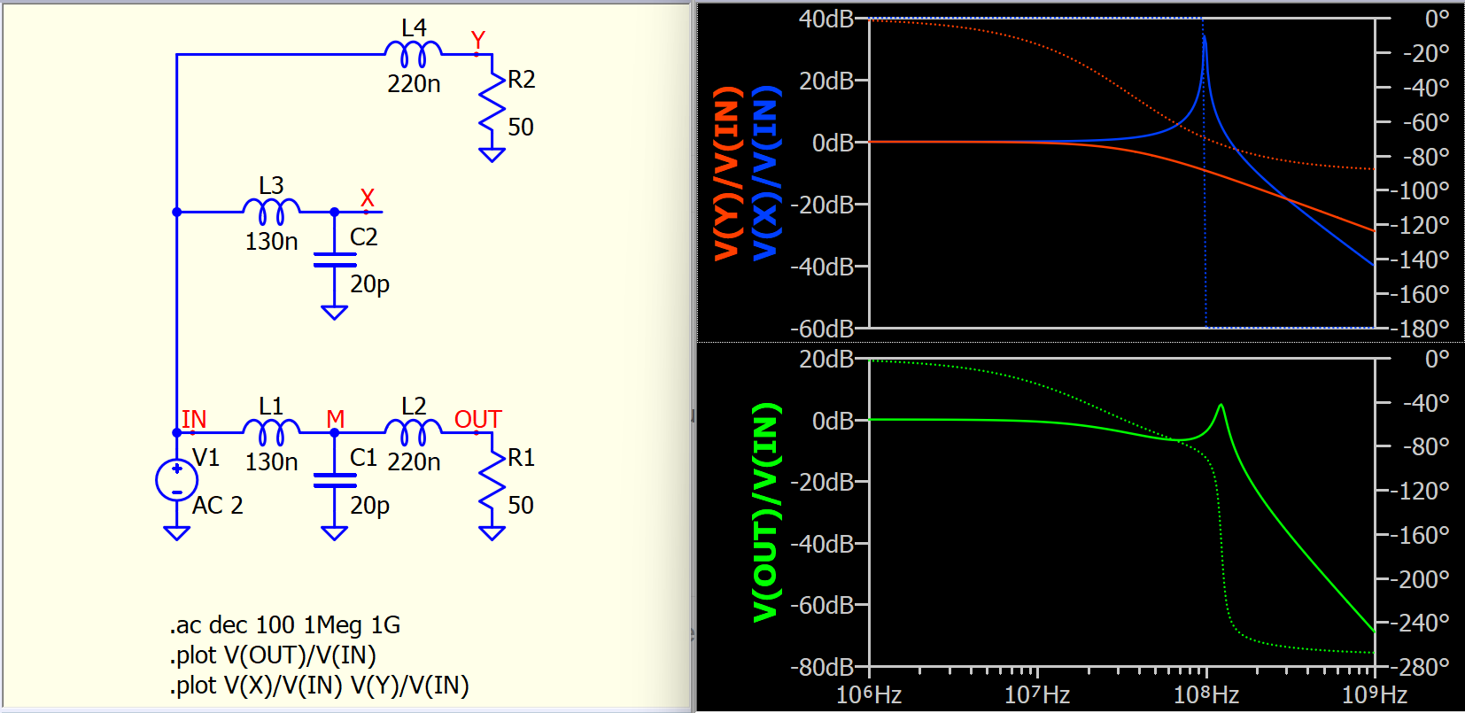
T-type filter with 2 inductors and 1 capacitor, which is third order. Anything higher than 1st order, you have to consider the damping factor.
To simply understand this filter, let’s break L1/C1 and L2 into two parts (this analysis is not correct in math, but it can help understand what you are dealing with). L1/C1 is a low-pass filter, but it forms a resonant without damping (no resistor), the gain is very high at its resonant frequency. L2 and a 50-ohm load is a 1st order low-pass.
Well, this is just a quick way to explain this filter shape; precise analysis requires deriving the transfer function formula.
T-filter.qsch (6.0 KB)
1 Like
The voltage source impedance must be used.
Thanks a lot Sir for clearing my doubt