I am trying to make a real time location tracking system, I have been following the gateway quick deployment guide: DWM1001 Gateway Quick Deployment Guide - Decawave . The only thing I haven’t done is create an RTLS network using the android application. This is because I don’t have an android device. I assumed however that this didn’t matter if I configured it over the UART connection, as it says in the guide:
PANS firmware offers APIs to create a network and configure nodes directly over the UART. For
advanced users, this method can be faster than configuring over the DRTLS Manager.
So I configured it via the UART connection, however when I use MQTT or access the proxy server, only the gateway is visible, the anchors and tags are not visible within the network. I assumed this was an issue with the network configuration so I attempted to download an android emulator but this doesn’t work with bluetooth. My question is, do I really need to purchase an android device in order to get this system working or is there any other way? Have I missed something? Thanks a lot.
Hi @maxwh21
first answer is no, you dont need to purchase an android device for configuring the PANS. I do have Android device but most of time Im using shell for configuration.
My best guess is that you have set different PANID for UWB network (AN + TN) and different PANID for bridge configuration. Check the /etc/dwm1001/dwm1001.config if the PANID here is the same as it is set in the AN’s.
If not please paste here the output of si command from TN, AN, ANI (initiator) and bridge.
Cheers,
JK
Cheers,
I checked that file and the panid is set to 0x1234, the same as the anchors, initiators and tags.
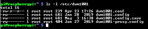
The only difference I can see between my setup and the gateway guide is when checking the files within the files on the pi there are 4 files as opposed to 2.
Hi @maxwh21
I cant take a look now. But Im pretty much convinced that there should not be dwm1001.conf which seems that you have edited and the dwm1001.config.save seems to be generated by some editor - not important.
You need to edit only the dwm1001.config - you have to be a root to be able to edit this file! For example sudo nano dwm1001.config
Cheers
JK
Here is the system information (SI) for the initiator node, and the Anchor node:
Here is the system information for the tag node, and the dwm1001.config file within the bridge node:
Here is the web server, that only can find the gateway and not the anchors and tags:

(Apologies for the weird formatting, I could only upload 2 links and one image per post)
The only option is that the panIDs are set as x1234 for the tags, anchors and initiators, and 0x1234 for the bridge node. However when setting it up I did set it as 0x1234 so I assume this is all well and good. Please let me know if you can spot any issues
Hi @maxwh21
this looks fine.
Questions:
- Which RPi version do you use?
- post here some messages from dmesg command (run this in linux shell)
- connect the USB cabe from the RPI to the mdek kit and then open the shell and post here the output of si command.
Cheers
JK
- Pi 3b
-
https://file.io/lU6ABWbmKNX5
will do 3 now
For 3) Do you mean connect to the pi via teraterm SSH connection to run the SI command or to run the SI command on the pi itself?
Hi @maxwh21
I need to see the SI output of the DWM1001-DEV that is connected to the RPI. Pretty much the same as you did with AN/TN. You can connect it to PC also and open teraterm to it too.
The file.io does not seems to be working - Im getting 504 Gateway time-out error. Just paste here cca 20 last lines from dmesg.
Cheers
JK
Here is the SI of the bridge

Here are the last 20 lines from the dmesg file
[ 88.916975] dwm spi0.0: reseting bridge manually
[ 88.917086] dwm spi0.0: dwm_reset failed, error -14
[ 88.917090] dwm spi0.0: bridge can’t be initialized, error -14
[ 92.665793] dwm spi0.0: decode TLV failed, error 2 t:0 l:0
[ 92.665801] dwm spi0.0: reseting bridge manually
[ 92.665909] dwm spi0.0: dwm_node_id_get failed, error -12
[ 92.665914] dwm spi0.0: reseting bridge
[ 93.202142] dwm spi0.0: decode TLV failed, error 2 t:0 l:0
[ 93.202150] dwm spi0.0: reseting bridge manually
[ 93.202260] dwm spi0.0: dwm_reset failed, error -14
[ 93.202264] dwm spi0.0: bridge can’t be initialized, error -14
[ 96.970667] dwm spi0.0: decode TLV failed, error 2 t:0 l:0
[ 96.970676] dwm spi0.0: reseting bridge manually
[ 96.970802] dwm spi0.0: dwm_node_id_get failed, error -12
[ 96.970807] dwm spi0.0: reseting bridge
[ 97.508109] dwm spi0.0: decode TLV failed, error 2 t:0 l:0
[ 97.508117] dwm spi0.0: reseting bridge manually
[ 97.508226] dwm spi0.0: dwm_reset failed, error -14
[ 97.508230] dwm spi0.0: bridge can’t be initialized, error -14
pi@raspberrypi:~ $
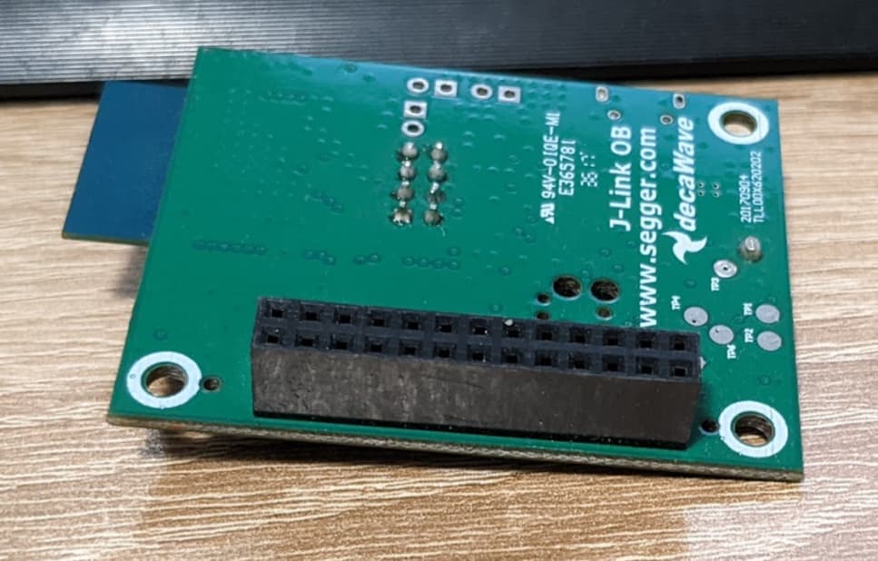
I read somewhere that other people have had similar errors when the soldering has not been correctly completing, I haven’t actually soldered the connection between the bridge and the pi, but it seems to still work, maybe this is the issue?
Hi @maxwh21
yes this is mostly related to the bridge header soldering. You must solder the header to the DWM1001-DEV and then connect it to the raspberry pi. See the images below.

Cheers
JK
Yeah perfect this has resolved the issue, thanks a lot for the help!