Hi
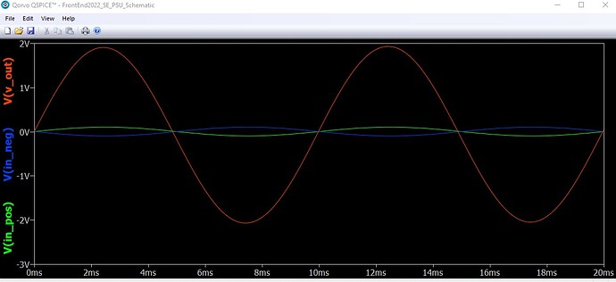
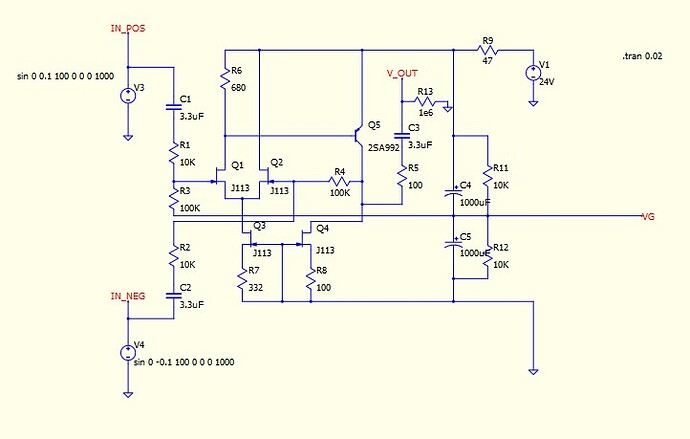
I wanted to check a few things on a schematic, calculating it with QSpice, found weird results compared to expectations (from the article explaining the schematics and people having built it).
A] Background / Context
This pdf article here https://www.diyaudio.com/community/threads/diy-front-end-2022.394339/
B]
- I first modeled it in QSpice, using J113 & 2SA992 models available online. It gave the expected results in terms of amplification.
- I then modified the circuit to have a Single Ended supply +36V, page 2 “To run the circuit with a V+ single-ended supply, set R10 at 0 ohms and treat the V- as
ground.”
Now, signal is amplified with a 18V DC offset. = not expected
C] Then i tried the same model in LT Spice, using the J113 model available in LT Spice and the 2SA992 model from the internet.
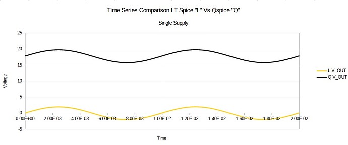
- Original schematic ran OK, a few mvolts difference between LT Spice and QSpice (see attached LibreOffice Calc sheet)
- Single supply version +36V ran according to the article expecation, no DC offset.
D] Finally, i copied the LT Spice J113 model into QSpice, made sure to use the same 2SA992 model in both LTSpice and QSpice.
Same result as C]1. and C]2.
=So i don’t understand the difference between LT Spice and QSpice.
E.]
One point: for 2SA992, i took a standard component available in QSpice and later modified it to call the specific 2SA992 model.
That’s a possible point of interest/mistake i guess.
But i am a bit at loss to understand the drastic difference between the 2 softwares and not finding the gross mistake i might be doing (to have such difference)
I am quite new to electronic modelling, coming from the 1D backressoure and acoustic, 3D mechanics and CFD.
Could somebody have a look to point out the obvious?
Files explainations
Models:
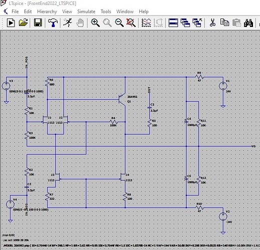
LT Spice reference “FrontEnd2022_LTSPICE” (+/- supply)
LT Spice Single Ended Supply “FrontEnd2022_SE_PSU_LTSPICE” (+36V supply)
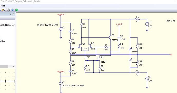
QSpice reference “FrontEnd2022_Original_Schematic_Article” (+/- supply)
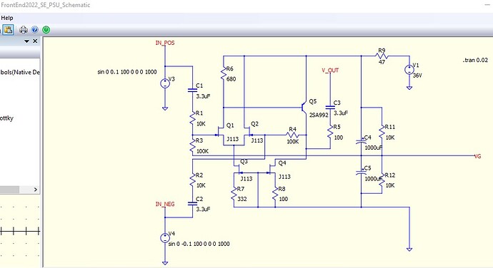
QSpice Single Ended Supply “FrontEnd2022_SE_PSU_Schematic” (+36V) [issue]
J113 coming from LT Spice library
2SA992 online model (could find a reference if needed)
Quick post-processing: LibreOffice calc with V_Out comparison
Edit: Sorry, as a new user, i can not upload attachments as i would like.
is is possible to grant the right to do so?
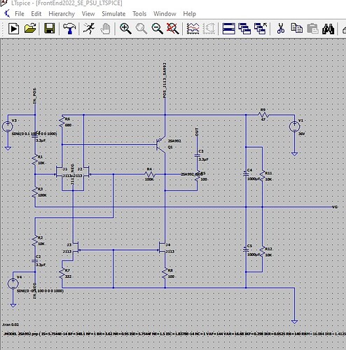
Q Spice Reference schematic
QSpice Single Supply version
LT Spice Reference Schematic (dual supply)
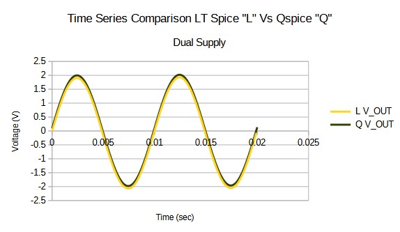
Comparison of the original schematic, LT_Spice Vs QSpice.
Looks reasonnably OK
In [B], where you locate J113 and 2SA992 model from internet?
In [D], you mentioned Same result as C]1 and C]2, do you means in Qspice, even you took transistor model same as LTspice, you still cannot get a same simulation result between LTspice and Qspice for single supply version?
Any chance you can share your simulation files with onedrive or dropbox?
Hi
Thanks for the quick answer.
-
Files available in this Onedrive folder https://1drv.ms/f/s!AhSczFPzqHlra8Cj-W2xSZx-2zQ?e=DiwVVp
a.Yes, i mean, i can not get the same simulation results between LTSpice and Qspice even when i take the same transistor model in LTSpice & QSpice.
b. For the uploaded models, i use
J113 model from LTSpice (direct in LTSpice, copied the text file from LT to make a text file for Qspice, uploaded)
2SA992 probably from here https://www.diyaudio.com/community/threads/emprit-amplifier.284005/page-2 (rematching the model to a google search)
- Models from the internet
a. J113 used is now from the LTSpice library (so, doesn’t make sense to speak about J113 model from somewhere else)
b. 2SA992 answered above.
In QSPICE, connect resistor 1MEG between V_OUT and GND.
1 Like
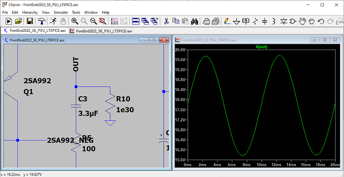
In additional to @test4piru reply, you can replicate DC offset from V(OUT) in LTspice if a resistor with very high resistance (>1e20) is added between V(OUT) and GND.
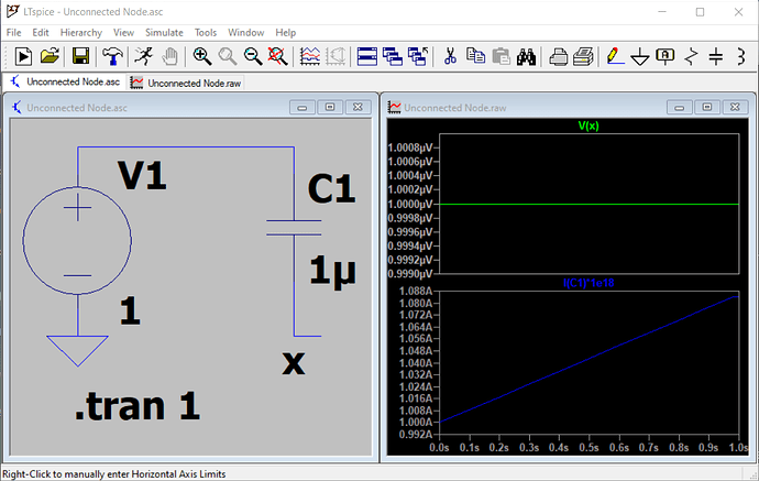
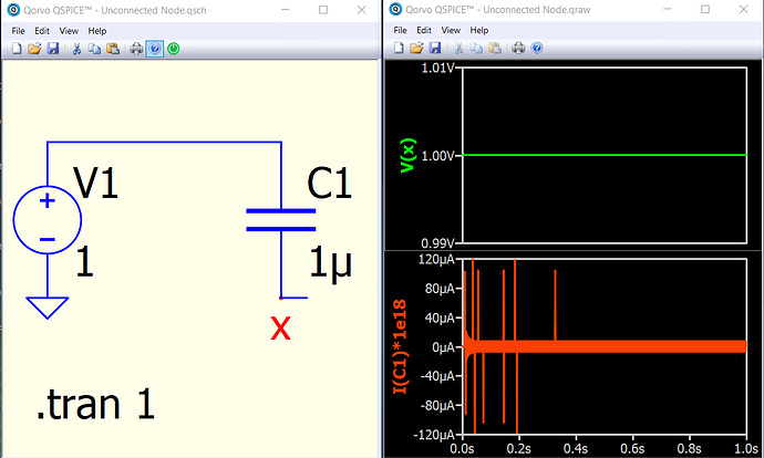
My guess is that, for LTspice, it will automatically add a finite resistor between unconnected node (for capacitor?) but not for Qspice. [If you run LTspice simulation, View > SPICE Error Log, you can see a Warning that C3 with less than two connections.] If I force a connection between V(OUT) and GND with R10=1e30 and simulation run with a DC offset in V(OUT), I tend to believe LTspice may automatically forced a resistor may be around 1e12 for unconnected node for capacitor, but just a guess.
Another method to force Qspice to run without DC offset in V(OUT) is to add a .option gshunt=1e-12 . This will add shunt resistor at each node. But I think add a load at V(OUT) as @test4piru mentioned is the best approach, as your circuit should connect to somewhere with a load in there.
Compare simulation result of LTspice and Qspice for capacitor with an open connection.
Ok, i put a 1 Mega Ohm resistor between V_Out and a Ground, got the same result for bipolar power supply (+/-) and single ended supply (only +)
I guess LT Spice was “too nice” to output something. If i see graphs, i would assume the calculation ran smoothly but i should have checked the logs!
With this, i will investiguate a bit on the LT Spice side but thank you some much for your joint effort to help!
Have a nice day
And with the same 1 mega ohm resistor, LT_Spice doesn’t give any warning.
So…thanks for the help!
