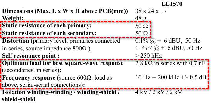
In this datasheet, it only provides static resistance of each winding, but without inductance. Static resistance is refer to series resistance of each winding. Possibly this part is constructed with a very thin wire with many turns. From this datasheet, winding inductance (i.e. primary or secondary inductance) is not provided, but can be expected as a very large number as its frequency response claimed that 10Hz to 200kHz with +/- 0.5dB change of gain. This transformer can still act as an effective transformer at 10Hz, its inductance has to be large!
Parallel resistance is not given, and in inductor/transformer model, parallel resistance is in general modeling the loss of core; may be can be ignored in this transformer modeling.
In short, with limited information from datasheet, it is a challenge in getting its model. But I still want to show you, how the frequency response in this datasheet can be simulated.
Frequency response states that, between 10Hz to 200kHz, gain is +/-0.5dB.
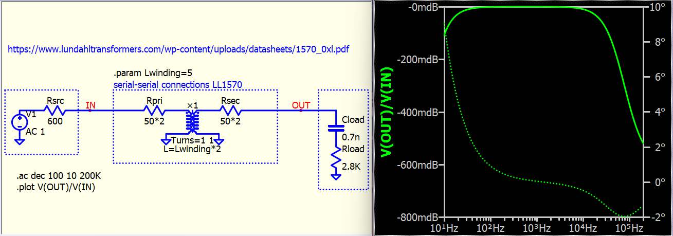
Test condition is that, source with 600ohms, this represents signal source with source resistance 600ohms; serial-serial connections, which represents two primary windings are connected in series. And the load is same as above, where secondary windings are connected in series, and with a load = 2.8kohms in series 0.7nF
As a results, we can setup a model likes this to verify if the gain can within +/-0.5dB.
You can see value are double as two winding are in series. Gain is refer to measurable output and input voltage relationship of LL1570.
In this setup, you can change Lwinding and can alter the frequency response.
You can use coupled inductor model or ×-Device. I don’t use Rser in ×-Device, as instance parameter of ×-Device only model primary side but not secondary, and in your case, for schematic to visually looks more understandable, I use external resistance to model both primary and secondary resistance.
LL1570 (coupled inductor model).qsch (5.5 KB)
LL1570 (×-Device).qsch (5.7 KB)