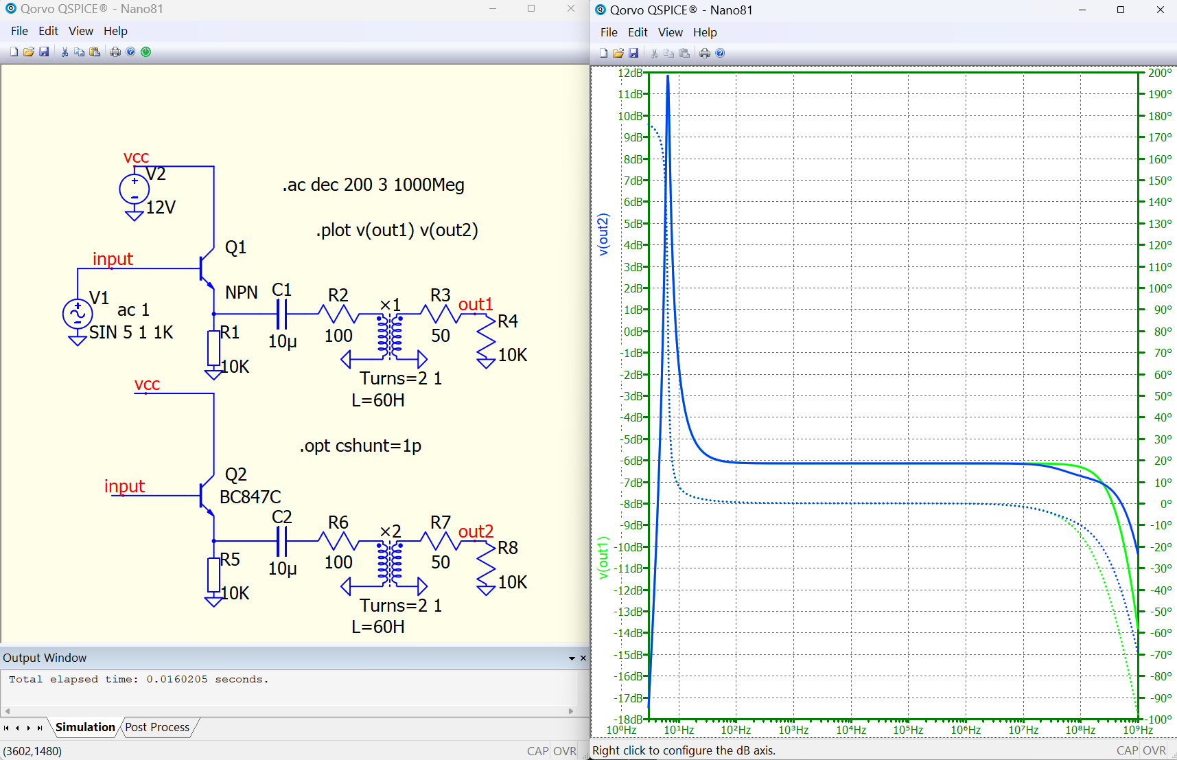
I have been trying to recreate simple amplifier schematics that have an output coupling capacitor that connects to output audio transformer. This usually results in my bode plot and THD looking the same as the original author. However, lately I have been trying to get more exact by trying to mimic the audio transformers specs, to get X-transformer to act just like the real life transformer. When I try to assign a (zero current primary inductance) value, the bode plot goes a little crazy in the low frequencies. The inductance of the primary creates a low pass filter with the output cap, that DOES NOT show in the schematic I am trying to copy. Here are some pics to show…
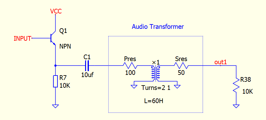
Typical output stage using coupling cap…
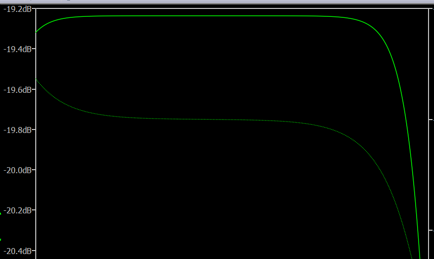
Here is the bode plot when I don’t use any X-transformer attributes…
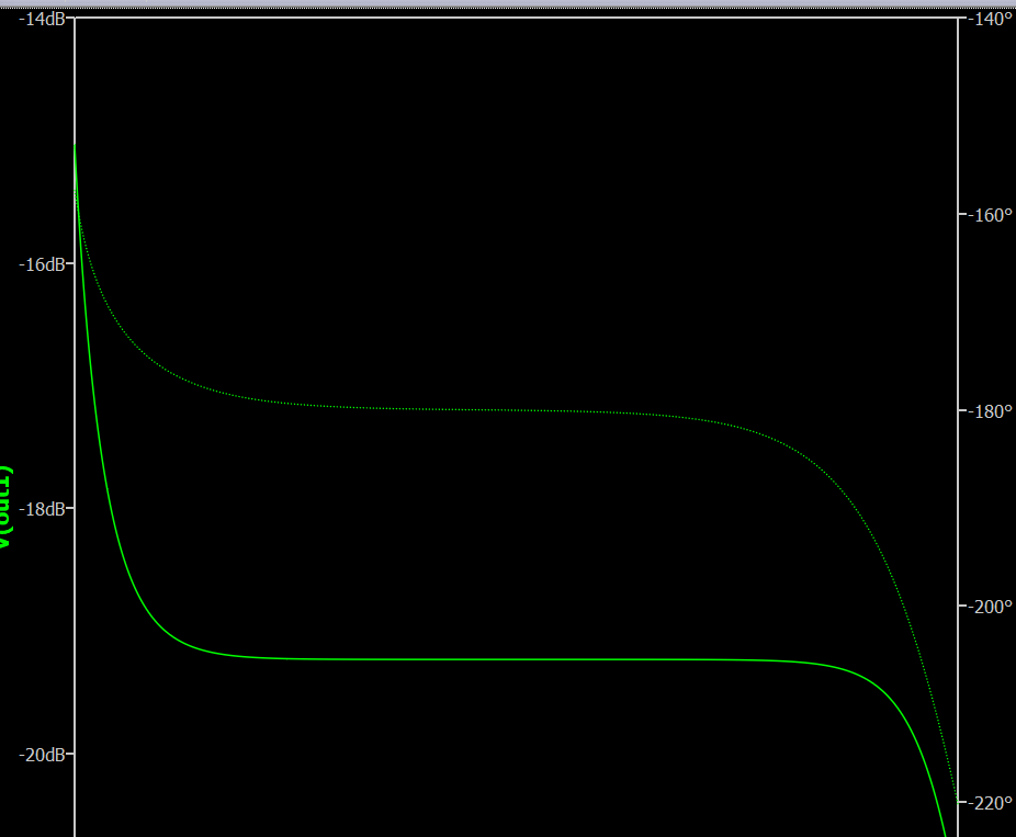
Here is the bode plot when I try to set a value for (L). In this case L=60H per the datasheet…
Can anyone help me understand this? Am I thinking of (zero current primary inductance) correctly. This happens in every amp schematic I try, regardless of any bypass caps before this stage. I know it’s not reacting with caps or filters in previous stages. What gives?