Hi, I’m trying to recreate the PWM circuit from the datasheet for the NE555, but I’m running into issues.
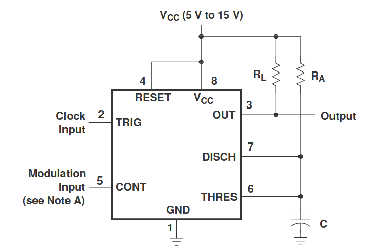
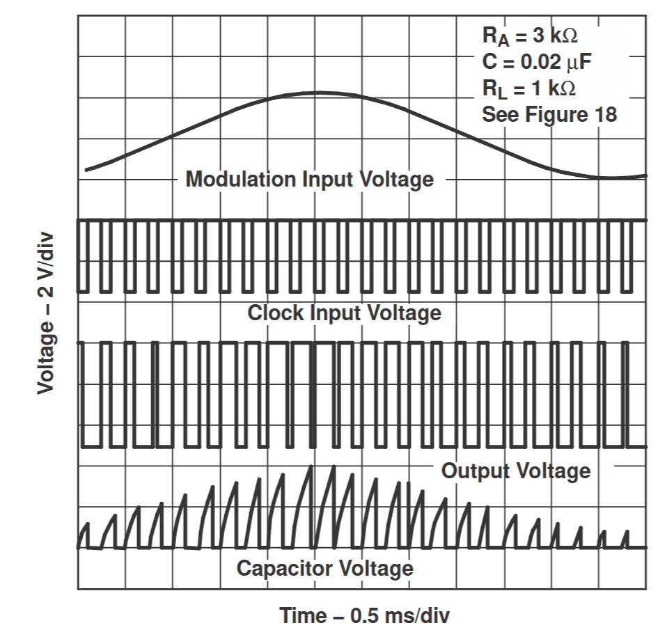
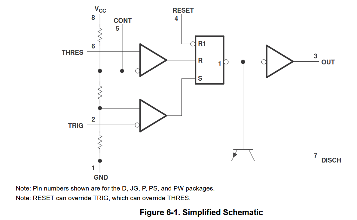
In the figure in the datasheet, the output goes high and discharge starts when the capacitor voltage falls below the control voltage, and discharge is held on until the next falling edge on TRIG, when the internal latch is set.
In simulation, discharge starts correctly when we pass CV, but is released as soon as the capacitor voltage falls below CV, leading to the output oscillating instead of staying low for the rest of the cycle.
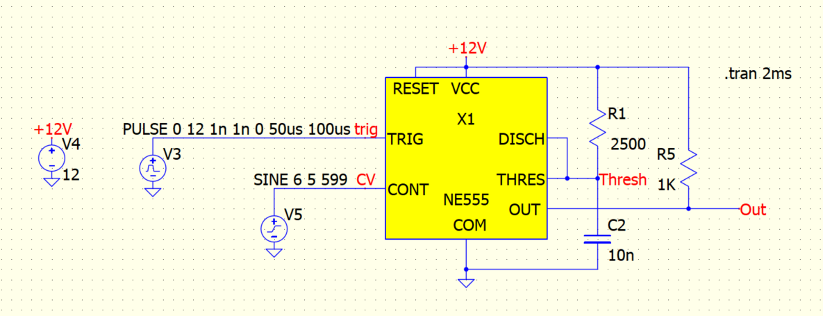
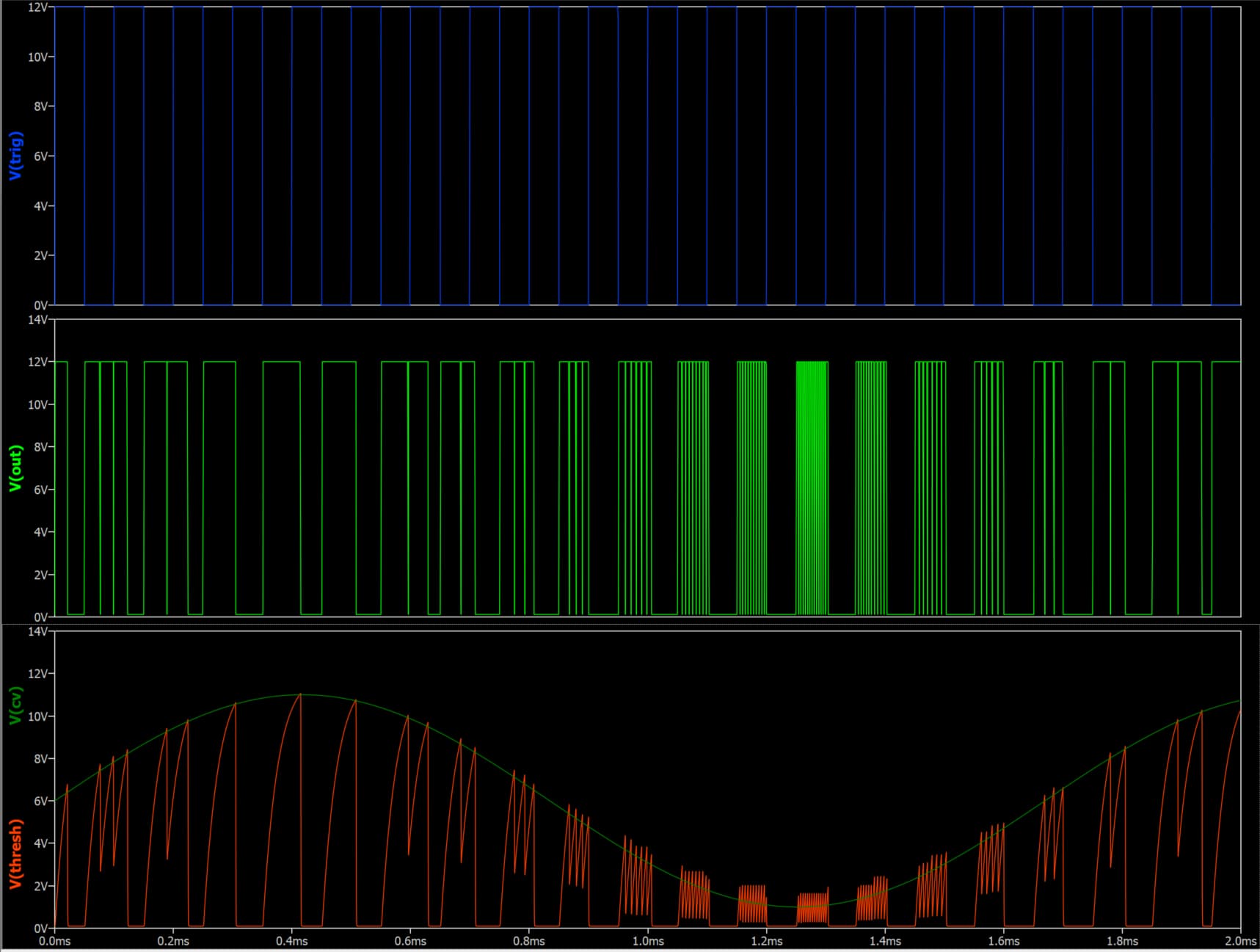
I recreated the NE555’s internal model as a schematic, and can see why this is happening, THRES overrides TRIG at the SR latch, initiating discharge, then when we discharge below CONT THRES falls and the latch goes back to Set, stopping discharge, and turning the output back on.
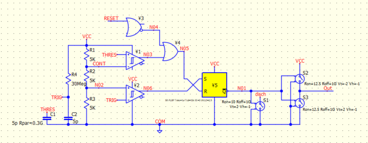
What I can’t see is why this wouldn’t happen for the real NE555. The main difference I’m seeing is the precedence for the latch inputs: “RESET can override TRIG, which can override THRES”, whereas in the QSPICE model, both THRES and RESET can override TRIG.
If TRIG overrides THRES, how can the latch toggle while TRIG is held low?
I’d upload my schematics but it looks like I don’t have permission to include attachments.
NE555 Datasheet: