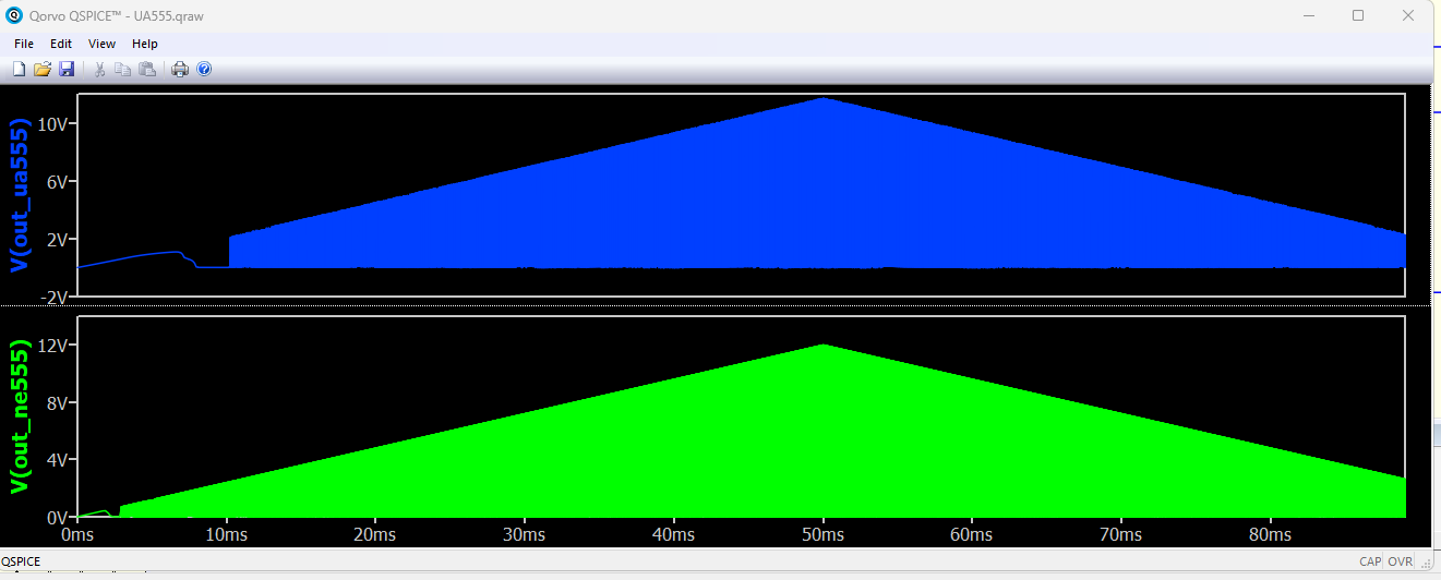
Please see the attached png file, I have found that in the NE555 behavioral model that the low voltage cutoff is much lower than in real world, I found a model that is working correctly , namely the UA5555.
Just a curious question: Are both behavioral models? Because the 555 has a lot of datasheet with internal schematic published, it may also be the complete circuit.
So if you do this simulation is there a big difference in run time for both models?
I noticed in the Qspice revision history that an update was made to the behavioral NE555 UVLO (Under Voltage Lock Out)
06/04/2024 Increased the behavioral NE555 UVLO
When examining the .subckt file, it can be observed that the UVLO is set at 2.5V for the RS flip-flop. Possibly, Mike saw your request and updated the behavioral model.
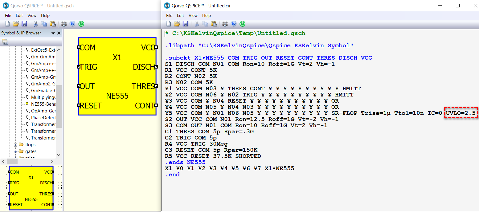
Yes Mike did see the request and he pushed a new update for that.
Now the part is simulating correct.