Hello All,
I would like to share my first attempt at making a PWM ic model.
I set myself the challenge of modeling the TL494 ic from the data sheet using the included devices in QSPICE. (I will explore C later)
My thought was not to make a perfect or accurate model of the TL494 but explore modeling methods and general approach. Please bare that in mind.
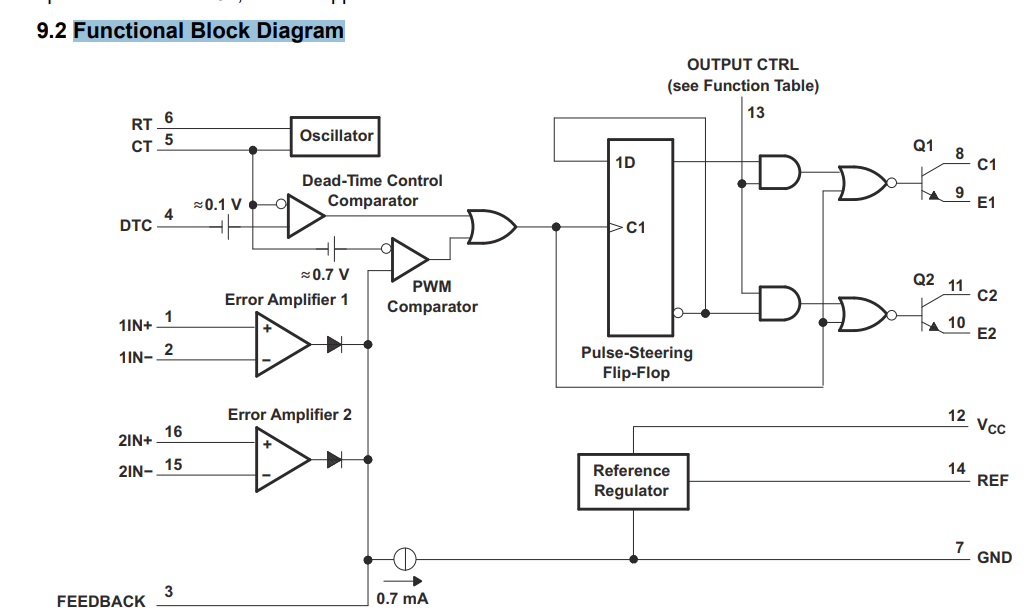
The first thing I noticed was my logic gate choice is a little different to the datasheet.
Is it fair to say that the data sheet Functional Block Diagram is a guide rather than accurate?
from TI data sheet:
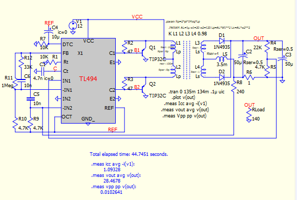
My attempt:
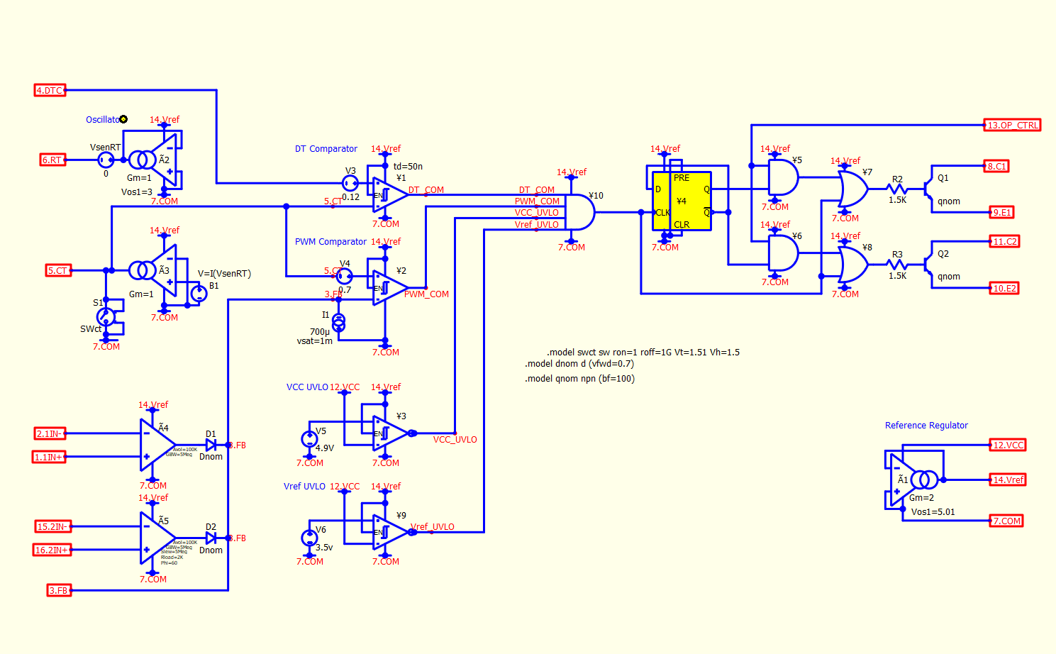
I open my effort to some friendly critique. (Please remember this is playful exploration not hard core modling)
TL494.qsch (40.7 KB)
Parent.TL494.qsch (8.4 KB)
Many thanks Ed.