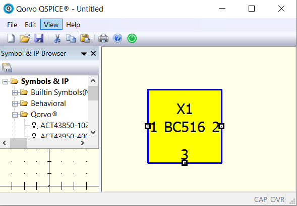
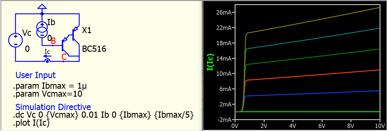
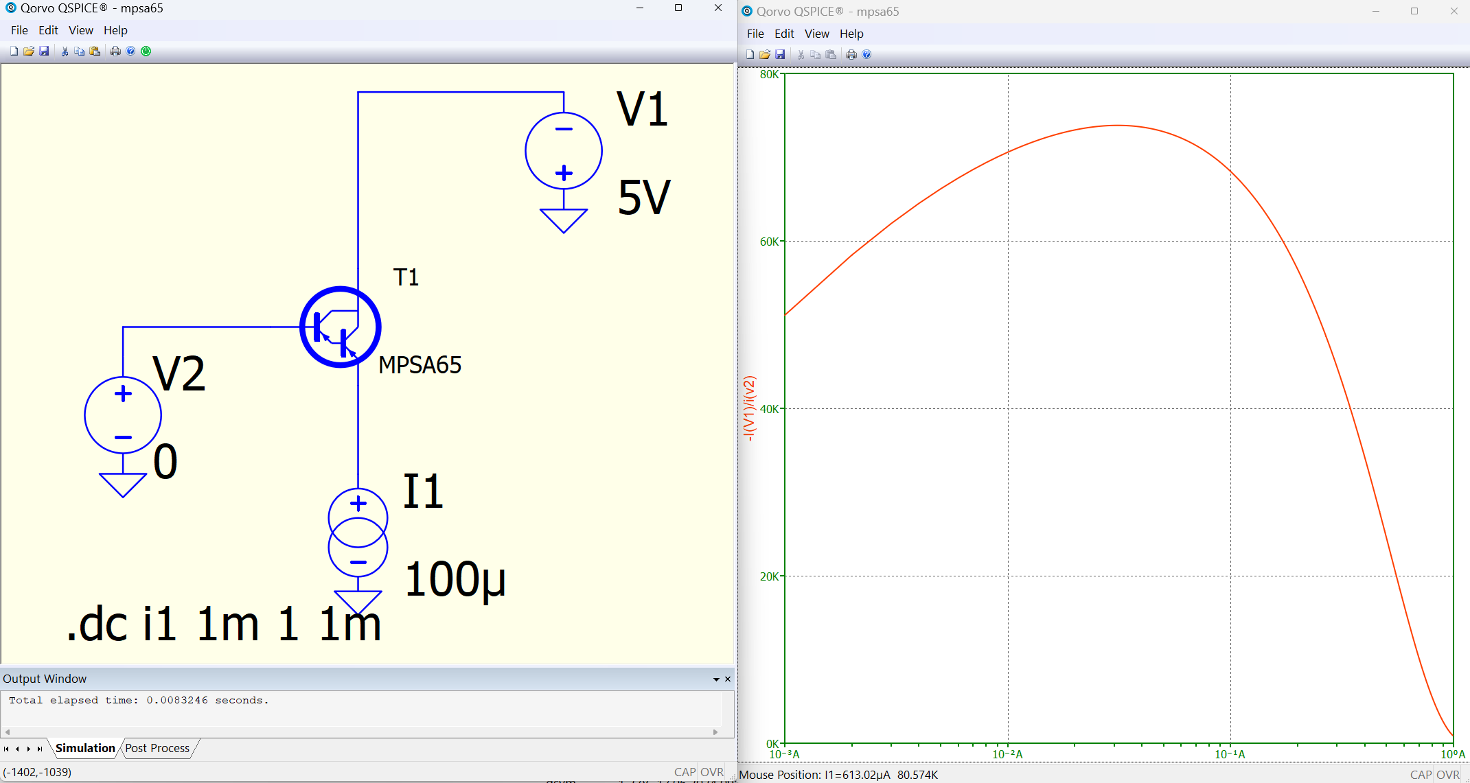
How do import a PNP darlington transistor subcircuit/model into QSPICE? The transistor is a MPS A65 (or MPSA65) (datasheet attached). A similar more recent transistor (BC516) uses the following .SUBCKT file
*** From file BC516.lib
********** Power Discrete Darlington Electrical Circuit Model **********
** Product: BC516
** Package: TO-92
**----------------------------------------------------------------------
* Connections: Collector
*              |  Base
*              |  |  Emitter
*              |  |  |
.SUBCKT BC516 1  2  3
Q1 1 2 4 Q1model
Q2 1 4 3 Q2model 3.128
D1 1 3 Dmodel
.MODEL Dmodel D
+ IS=1.000E-14    RS=1.000E-3     N=1         XTI=3
+ CJO=1.000E-20   VJ=1            M=0.5       FC=0.5
+ BV=110          IBV=1.0E-4
.MODEL Q1model PNP
+ IS=5.194E-11    BF=3.099E3      NF=1        VAF=60
+ IKF=1.503252    ISE=3.470E-13   NE=1.0      BR=0.101
+ NR=1            VAR=100         IKR=0.05    ISC=2.055E-10
+ NC=1.5          RB=0.0011       IRB=1E-7    RE=0.0241
+ RC=0.0043       CJE=1.800E-14   VJE=0.55    MJE=0.63
+ TF=1.971E-9     XTF=1           VTF=10      ITF=1.00E-2
+ CJC=1.600E-11   VJC=0.42        MJC=0.48    FC=0.5
+ TR=1.000E-8     XTB=1.58        EG=0.66
.MODEL Q2model PNP
+ IS=5.194E-11    BF=3.099E3      NF=1        VAF=60
+ IKF=1.503252    ISE=3.470E-13   NE=1.0      BR=0.101
+ NR=1            VAR=100         IKR=0.05    ISC=2.055E-10
+ NC=1.5          RB=0.0011       IRB=1E-7    RE=0.0241
+ RC=0.0043       CJE=1.800E-14   VJE=0.55    MJE=0.63
+ TF=1.971E-9     XTF=1           VTF=10      ITF=1.00E-2
+ CJC=1.600E-11   VJC=0.42        MJC=0.48    FC=0.5
+ TR=1.000E-8     XTB=1.58        EG=0.66
.ENDS
**----------------------------------------------------------------------
** Creation: Apr.-11-2011   Rev: 0.0
** Fairchild Semiconductor
How can I import this into QSPICE by pasting onto the schematic in the same way as I do with a .MODEL file? Would this BC516 be a suitable replacement for the MPSA65? I’m simulating a class A headphone amp from a HiFi News & Record Review article from January 1979. I will share this later on but I have to create the schematic first. I hope someone can help. Thanks.
mpsa14-mpsa66-datasheet-micro-electronics.pdf (144.1 KB)