I have a question about the dissipation power generated for the SiC FET devices provided by QSpice.
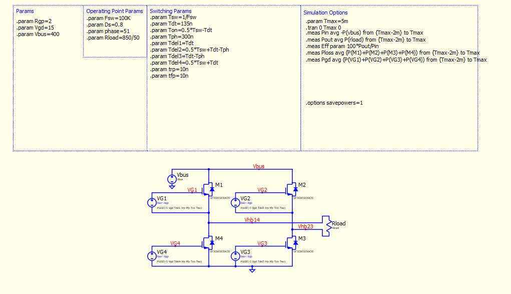
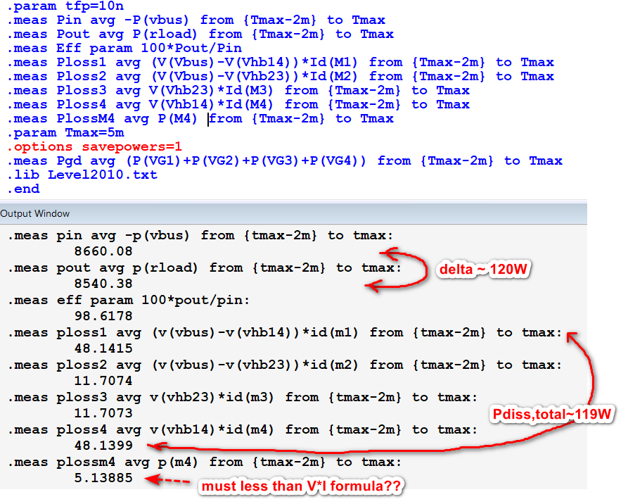
In this simulation, the sum of the average power dissipated by all 4 FETs (Ploss measurement) is not even close to the difference between the input power (Pin measurement) and output power (Pout measurement). As far as I can tell, the FETs are the only component here which will cause losses. Does anyone know what the cause of this discrepancy is?
Netlist:
VG1 VG1 Vhb14 PULSE(-5 Vgd Tdel1 trp tfp Ton Tsw)
VG4 VG4 0 PULSE(-5 Vgd Tdel4 trp tfp Ton Tsw)
VG2 VG2 Vhb23 PULSE(-5 Vgd Tdel2 trp tfp Ton Tsw)
VG3 VG3 0 PULSE(-5 Vgd Tdel3 trp tfp Ton Tsw)
Vbus Vbus 0 Vbus
Rload Vhb14 Vhb23 Rload
M1 Vbus VG1 Vhb14 ¥ UF3C065030K3S NMOS
M2 Vbus VG2 Vhb23 ¥ UF3C065030K3S NMOS
M3 Vhb23 VG3 0 ¥ UF3C065030K3S NMOS
M4 Vhb14 VG4 0 ¥ UF3C065030K3S NMOS
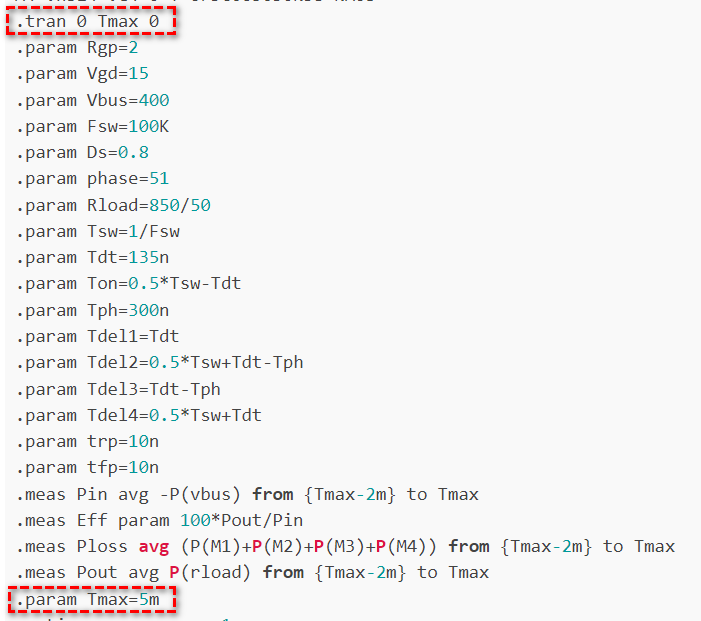
.tran 0 Tmax 0
.param Rgp=2
.param Vgd=15
.param Vbus=400
.param Fsw=100K
.param Ds=0.8
.param phase=51
.param Rload=850/50
.param Tsw=1/Fsw
.param Tdt=135n
.param Ton=0.5*Tsw-Tdt
.param Tph=300n
.param Tdel1=Tdt
.param Tdel2=0.5*Tsw+Tdt-Tph
.param Tdel3=Tdt-Tph
.param Tdel4=0.5*Tsw+Tdt
.param trp=10n
.param tfp=10n
.meas Pin avg -P(vbus) from {Tmax-2m} to Tmax
.meas Eff param 100*Pout/Pin
.meas Ploss avg (P(M1)+P(M2)+P(M3)+P(M4)) from {Tmax-2m} to Tmax
.meas Pout avg P(rload) from {Tmax-2m} to Tmax
.param Tmax=5m
.options savepowers=1
.meas Pgd avg (P(VG1)+P(VG2)+P(VG3)+P(VG4)) from {Tmax-2m} to Tmax
.lib Level2010.txt
.end