I have a circuit that needs a fuse and some transient protection devices. I want to model various actions around blowing the fuse. I want to model the I^2*t performance because I learned about it the hard way.
Short war story: My automotive design had a fast-blow fuse larger than the circuit’s measured current draw. Everything was working well until the customer returned all units with blown fuses. My lab bench power supply was drooping as my circuit’s input filter caps were being charged at power-up. Their car battery didn’t droop.
Here are the references:
Prof. Sam Ben-Yaakov has a YouTube video that explains the I2t of a fuse. Not about how to model, but a good reference to understand I2t.
I2t. What? Why? When?: The electric fuse case - YouTube
For a quick navigation in google, if I plan to work on fuse modeling for my project, possibly this is where I would begin.
Simple fuse SPICE model - NI Community
There are more complicated fuse models that rely on thermal parameters, but I don’t think these parameters can be found through the datasheet.
NL 21
5314bc45ae2070036780e9ecd48ca414.pdf
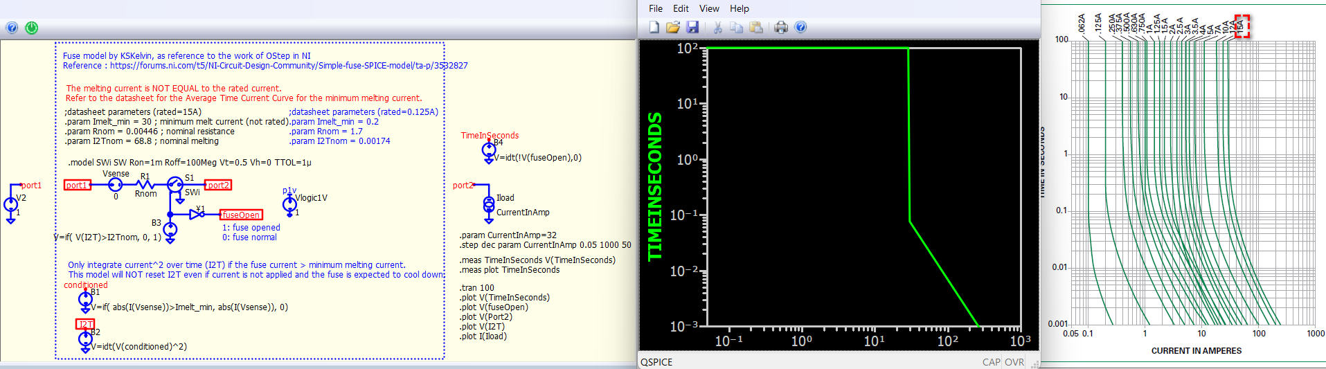
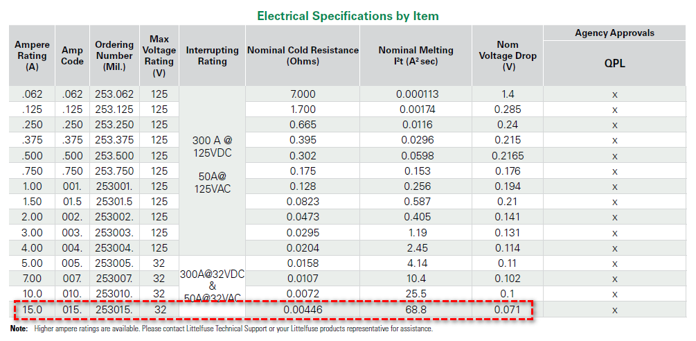
As per the simple fuse model mentioned earlier, it assumes that I2T is constant across the current range. For example, the Littelfuse 253 Series datasheet (253 Series PICO® Fuses - Axial Radial Thru Hole Fuses | Littelfuse), when you refer to the Average Time Current Curves, you will notice that I2T is not a constant term. The datasheet specifies it as a nominal value. The nominal I2T essentially serves as a linear approximation at higher current amplitudes in the Average Time Current Curves.
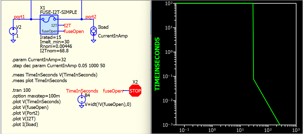
Moreover, the minimum melting current should be determined by referring to the Average Time Current Curves (i.e. current asymptote), and it is not the same as the rated current. Here is an example of how to incorporate datasheet parameters into the model. However, please be aware that this model integrates current over the entire simulation as long as this current exceeds the melt current. This model is not intended to simulate complex behaviors such as the fuse cooling down after a high inrush current, which would require a thermal model for such simulations. But such detailed information is not available in the datasheet.
I believe that fuse simulation is more of an approximate simulation, and in your application, the primary goal is to understand the I2T for inrush currents to ensure proper derating in fuse selection.
concept.Fuse-I2T-Simple.qsch (11.1 KB)
concept.Fuse-I2T-Simple.meas.pfg (162 Bytes)
This fuse symbol can be download from my Github.
Fuse-I2T-Simple.qsym · KSKelvin-Github/Qspice
Hi Kelvin.
Can i use your fuses models in an article of mine, to publish to Internet?
In order to simulate the behaviour of fuses.
Of course, i will write your name.
Thank you very much.
Giovanni Di Maria
Fuse-I2T-Simple.qsym
oh, thanks. Idea of this fuse symbol is based on another post by Ostep in NI forum, which is quoted in my schematice drawing. Feel free to use the symbol I created, with or without mentioning me is not important.
I think if you can include a link to the reply above, where I explained this symbol will be helpful to other, as this fuse model is a bit unique and there are limitations. It is the reason why I included the concept schematic in this case.
Share your article with us! ![]()
Thank you very much.
I am writing a collection of article about Power Electronics with QSPICE, on powerelectronicsnews.com.
Here’s the link of the collection:
https://www.powerelectronicsnews.com/author/giovanni-di-maria/
The article with fuses will be number 11, and it’ll published on June.
Than you very much.
Giovanni Di Maria
1 Like