Hi,
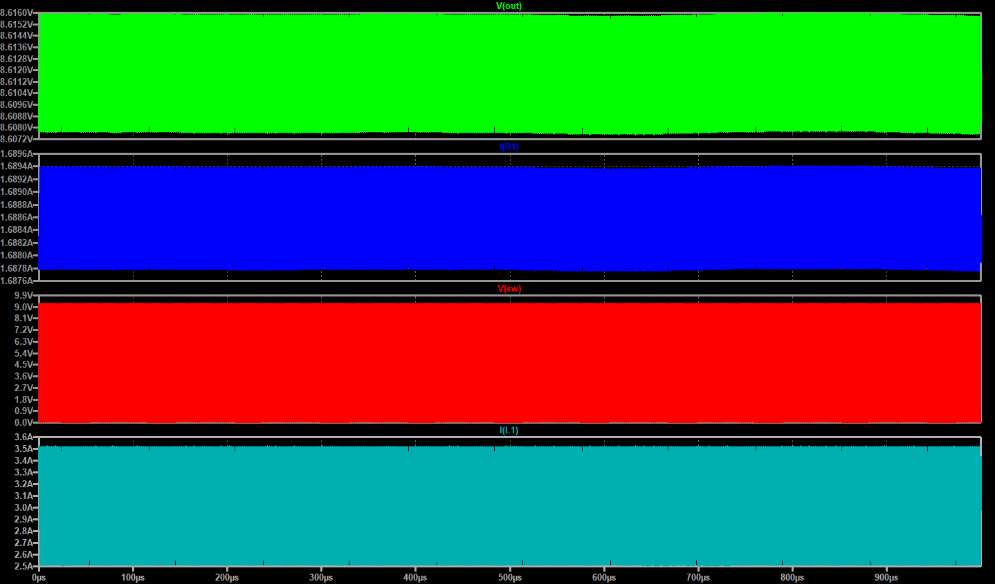
QSPICE results:
Untitled.qsch (15.6 KB)
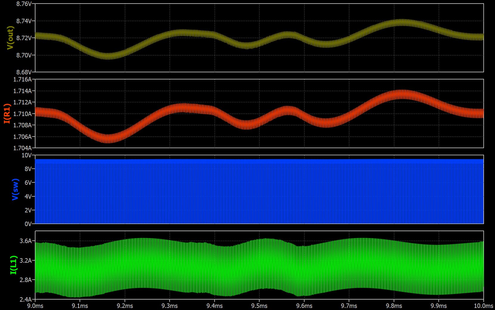
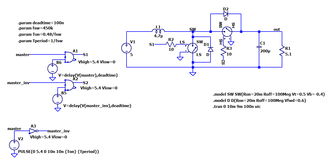
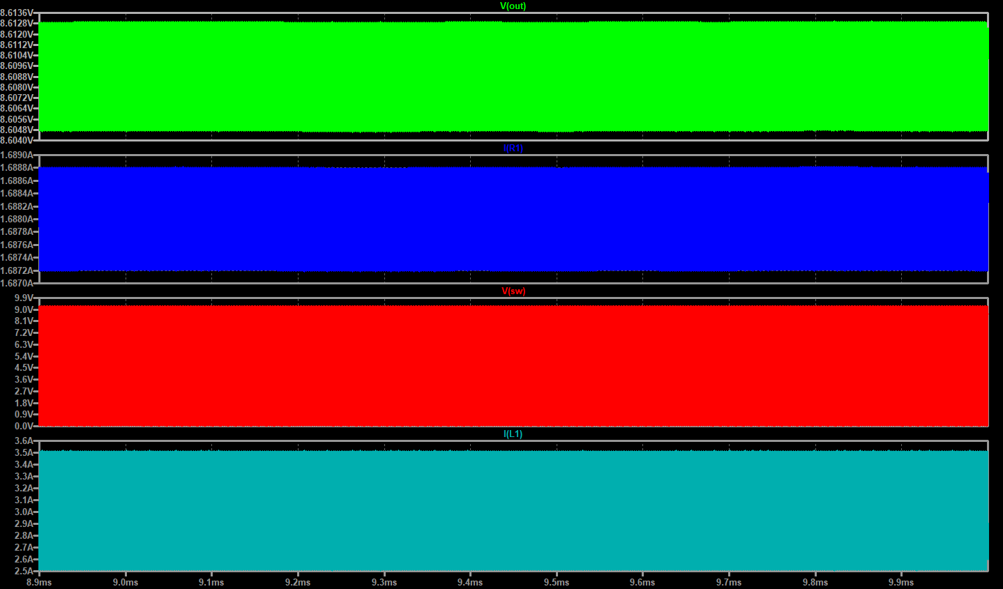
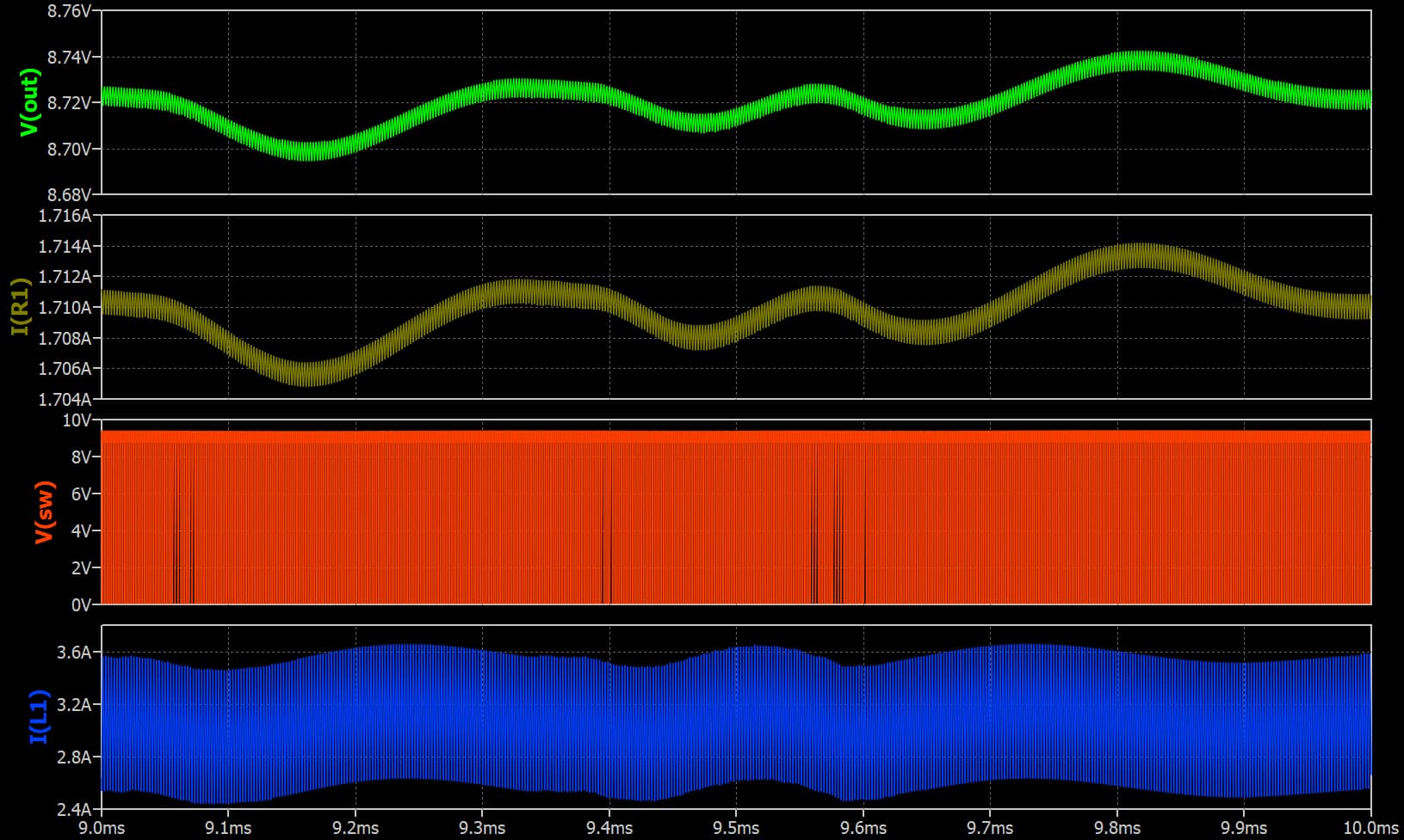
LTspice results:
This is when I run in LTspice with.tran 0 10m 0m 100n uic and zoomed between ~9ms and 10ms, and clicked on Autoarange Y-axis. If I make the same thing in QSPICE i obtained the same above results.
So, where is the mistake?
Have you tried to add ttol paramater on each logic gate in Qspice?
Be more aggressive in TTOL (set to 1ps), include SW S1 and S2.
I believe LTspice and Qspice with different timestep strategy, especially introduce of TTOL in Qspice.
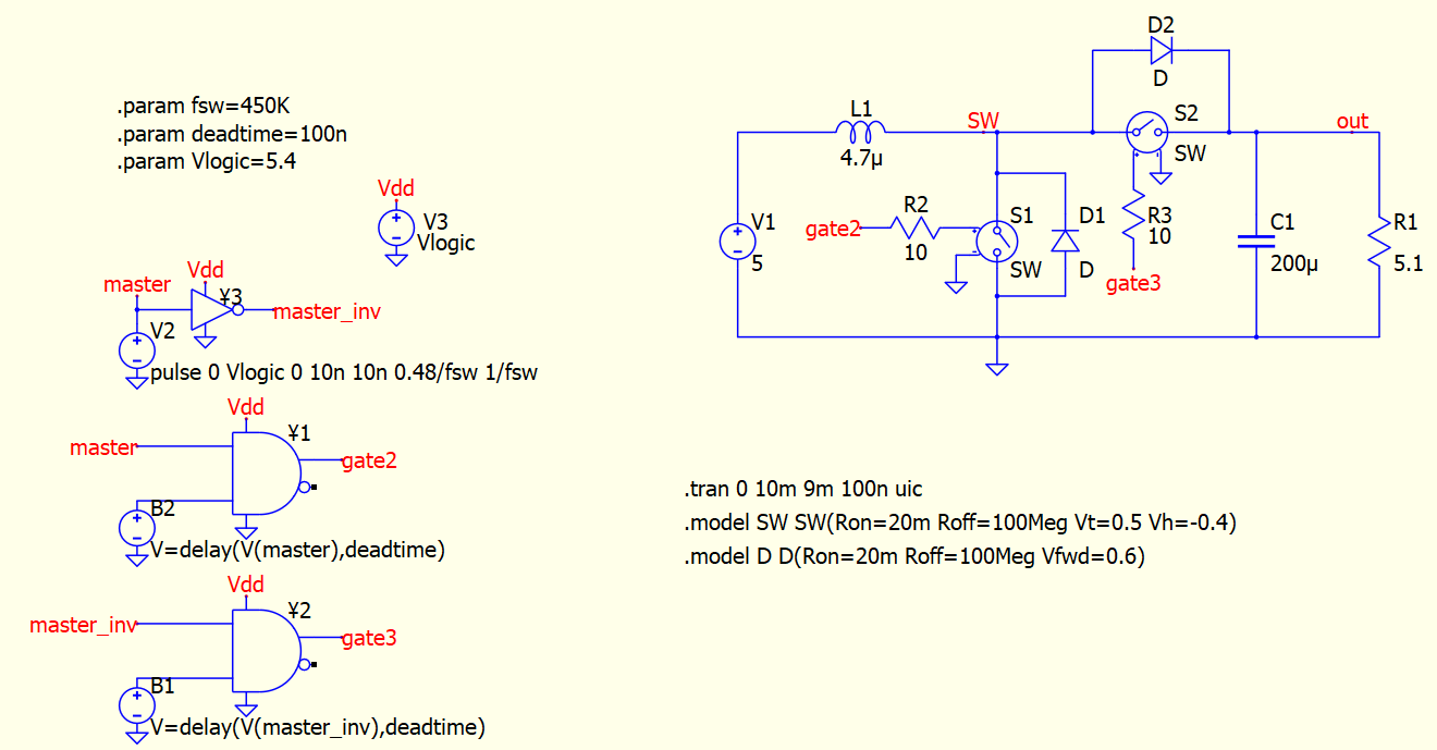
Your switching frequency is 450kHz and with 100ns deadtime, and with delay function for deadtime control. Timestep at switching moment become very essential.
R2 and R3 are not needed in this setup, with or without that shouldn’t affect the simulation.
Just curious, how many seconds LTspice is required to simulate this circuit from your testing?
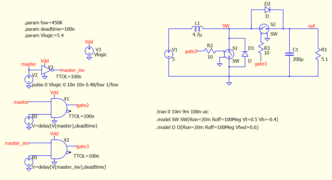
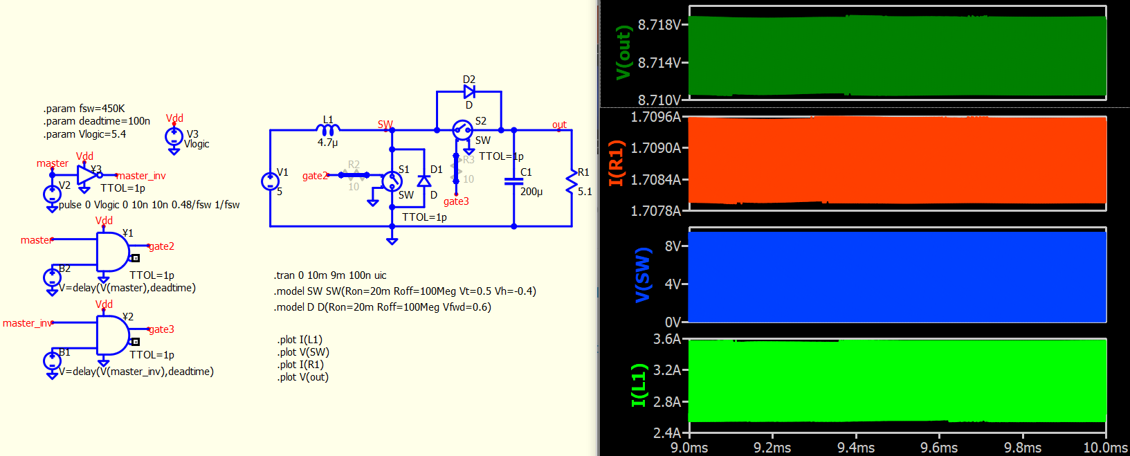
Boost with TTOL.qsch (16.0 KB)
With: .tran 0 10m 9m 100n uic
![]()
In LTspice there is TTOL?
And in QSPICE, when to know when it is necessary to put TTOL and at which components?
You need the ttol to be around 25% of your deadtime… So 25ns or lower
In his case, to get a relatively smooth envelop waveform from 9ms to 10ms, ttol needs to be around deadtime/2000. Here is a schematic with .param ttol to play with.
Sorry, ttol of S1 and S2 can be removed in this setup.
Sometime, I just very aggressive setting ttol to 1ps to see if thing work. After that, tune it back to optimize simulation time.
Boost with param TTOL.qsch (16.1 KB)
Does this TTOL parameter lengthen the simulation time? And can affect TTOL parameter simulation in negative way somehow?
Because if it does not increase the simulation time, and has no negative effect, then we can include in any component that has this parameter always in the simulation, right?
Are you aware if ttol in switch really work or not?I was making a comparator using a switch and pull up resistor, but it wasnt working properly…
At that time, I was hoping if it can be faster than using schmitt element… But failed
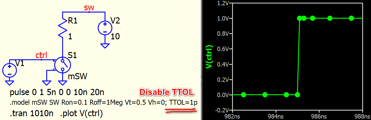
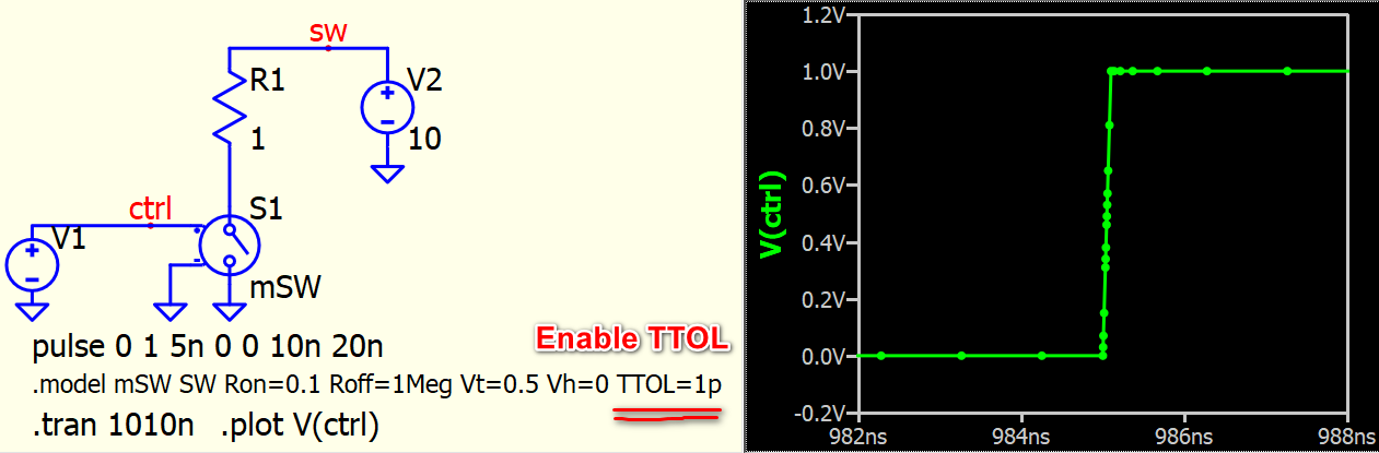
TTOL in switch operate properly. This is my test template to verify if TTOL in Switch is effective or not. In principal, to verify TTOL, simulate a long run in .tran from 0s, and zoom in to verify if extra timestep is added.
But beware where a TTOL device should locate for comparator. Adding TTOL in switch may not have effect to comparator trigger moment. I have comparators example in my symbol library, with a pdf explanation. You can have a look if it offer a better response.
Qspice/Symbols at main · KSKelvin-Github/Qspice
Switch - TTOL.qsch (3.8 KB)
Kelvin, can you show also the difference in having Vh positive value, negative value compared with Vh=0?
@Cornel download the device guideline, search S. Voltage Controlled Switch.
Qspice/Guideline at main · KSKelvin-Github/Qspice