We have a large simulation where we want to try running a .bode analysis. We put QSPICE on one of our large computers which has 3 TB of memory. When we try to run the simulation QSPICE posts an error :
Fatal error: realloc: can’t allocate 671088640 bytes.
That isn’t a lot of memory but we are not sure how to resolve this. I wanted to verify that QSPICE has no such limitation. It appears to be a 64-bit executable so it should have access to gobs of memory.
The .bode or .fra analysis run on post processing, thus you need to store all the datapoint at all perturbation frequency… once your data goes beyond a few GB, the post processing will take forever.
This is one solution for you, I developed FRA analysis that run on the runtime. You dont even need to store any waveform.
You may see that, in my example that the tran directive is “.tran 0 100 0 1u .uic”
The idea is, I dont need any waveform to be stored, and the FRA block can stop the simulation once you are finished
Thanks! That is worth a try. I’ll see what I can make of it.
“a few GB” - right now we weren’t really getting that far even. We were hoping a very powerful computer could still solve using the built-in QSPICE FRA methodology. I was mainly wondering if anyone had bumped into these limits before or if we are doing something wrong? I am still unclear why we can’t tap more memory.
Hi!
Out of curiosity, what kind of loop are you running “.bode” simulations?
…I’m sorry, I’m not addressing your 670MB challenge in this post…
Recently, I’m running a couple of projects for voltage regulator loop analysis in Time-Domain and I’m wondering if that helps. I have two (2) draft-stage technical articles to publish “soon” from my projects.
As we all confirmed by now, QSPICE is very fast simulator, especially faster than other simulators in .TRAN operations. I’m building an eco-system to extract loop info from time-domain only.
If you don’t mind, please share your high level concepts of your project using “.bode”.
@physicboy - wanted to thank you for the FRA code/circuit. We were able to get this to run on the original circuit that was problematic using either .bode or .fra analysis. We made a few adjustments to the settings, used the .save directive to avoid generating large qraw files and we were able to get some nice looking plots. They look correct.
@masashi.nogawa sorry we are not able to share the circuit, but it’s just a multiphase buck converter circuit we had built.
@physicboy If you don’t mind, i’d also like to understand how you came up with using TTOL=-1 ? That seems unusual to me. It almost seems like you are trying to roll-back the time by 1 second if you detect that the next call to your DLL would have some state change with present state.
@jordankman Thats great to know… Glad it works well for you.
the ttol parameter in FRA block is used to let the block to force simulation time step to be within a certain tolerance. To improve the sinewave accuracy.
*i honestly cant recall the exact detail out of my mind… Its been a while since I work on that block
However, when the ttol is -1, it simply means the FRA block wont force any timestep. For switching converter, the pwm should force very small timestep already, thus ttol in FRA is not necessary.
My project, on-going, is fully time-domain base not using sine-waves in time-domain.
In short, we know we can evaluate a loop stability from load transient test, I’m upgrading it.
My project is not packaged / wrapped up yet, I’ll share mine soon in a range of weeks.
@masashi.nogawa that’s great with what you said that you are trying to do above, but please share your projects also with us here after when you finish…
@physicboy thanks for the explanation. So -1 basically is a no-op. Why not just comment out that portion of the code instead? No concerns here, just wondering.
@masashi.nogawa I’d be happy to try your time-domain methodology out if available sometime. Are you doing it from step-response?
Do you have some reference articles where is described this? Or can you say some thoughts about how did you plan to evaluate the loop stability from load transient test?
Well…, I am writing the article of my project, right now, together with debugging/cleaning my C++ code It will be published soon under my series article from Microwave Journal.
My implementation is in line of my other article this one. Instead of actual testing, I’m doing the same/similar in QSPICE.
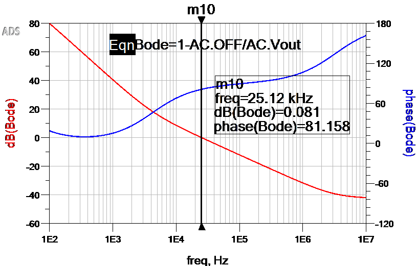
NOTE: Today, I found that the last figure (was on my draft) is missing at PSD site…see below plot. We can get this re-constructed from my step test on the bench.
I’m doing very basic from electronics textbooks: By knowing quality factor “Q”, we also know how many ringing peaks we must have in time-domain impulse or step response waveforms.
In the reverse way, from ringing peaks, we can obtain the “Q”, thus we can get phase-margin quantified.
@jordankman yes I can simply comment off in program. However, I dont want to open the Cblock and find the ttol line and comment it out. It is easier for user to modify it from outside.
The 1st one is using a C++ block and run a step response and re-constructing the output impedance. Here, my C++ code is controlling the time-step so to have finer resolution at the event of load stepping.
I started this article with a regular PWL source (of no time-step control, no C++ block) and I do see we need finer step control to get accurate results.
I’m writing the 2nd one where I’m using switching regulator model. Without making an averaged state model, we can evaluate the loop.
This SEPIA module (QSPICE C++ module) can extract the loop parameters directly from one step-response simulation.
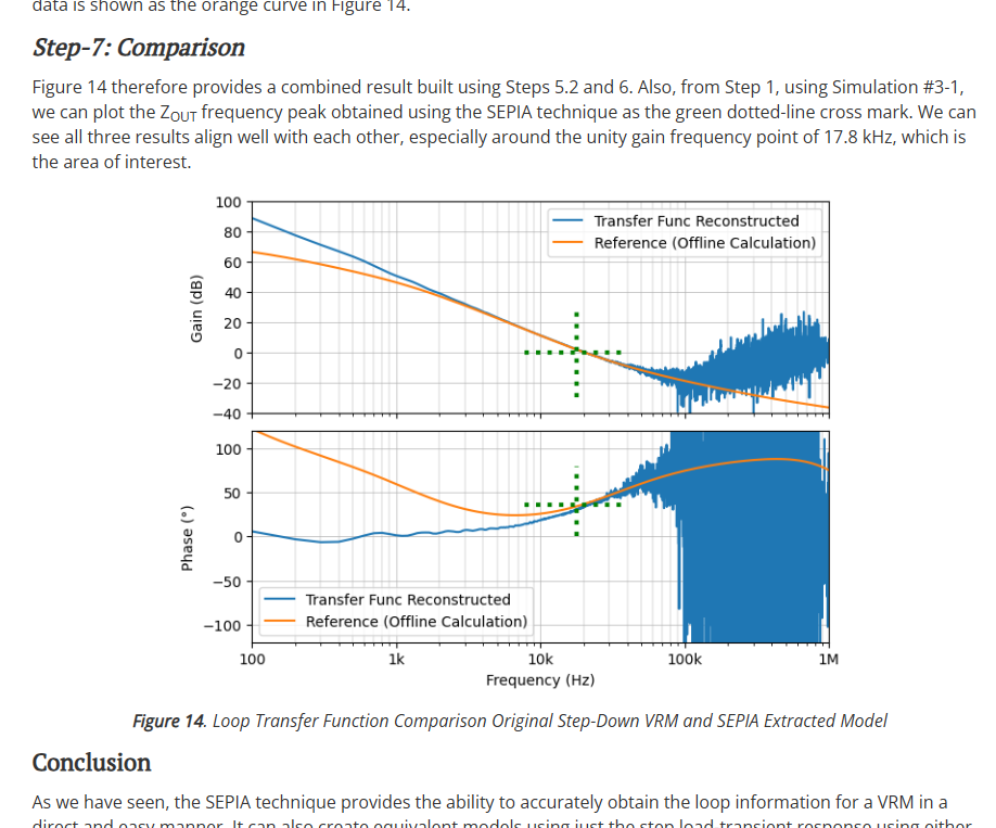
My 3rd simulation example in the article shows it can get unknown step-down regulator loop info.