I designed the new model in isolation With TL431 AND PC817B
But the circuit did not work well.
I think the problem is with the input and output ground?
test push pull - ABv6.qsch (38.1 KB)
You’re making it difficult to help. You use model files that are not attached to the diagram!
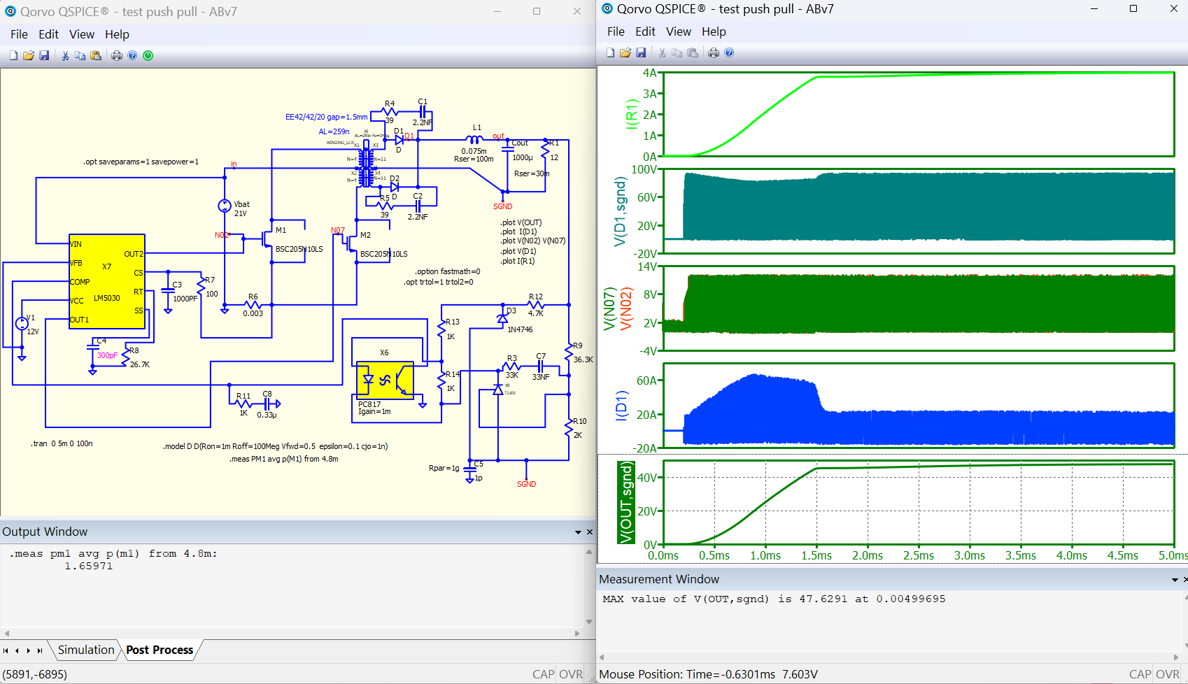
test push pull - ABv7.qsch (39.6 KB)
how can attached to the diagram!
In this simulation, the waveforms of my circuit are very different from your circuit.
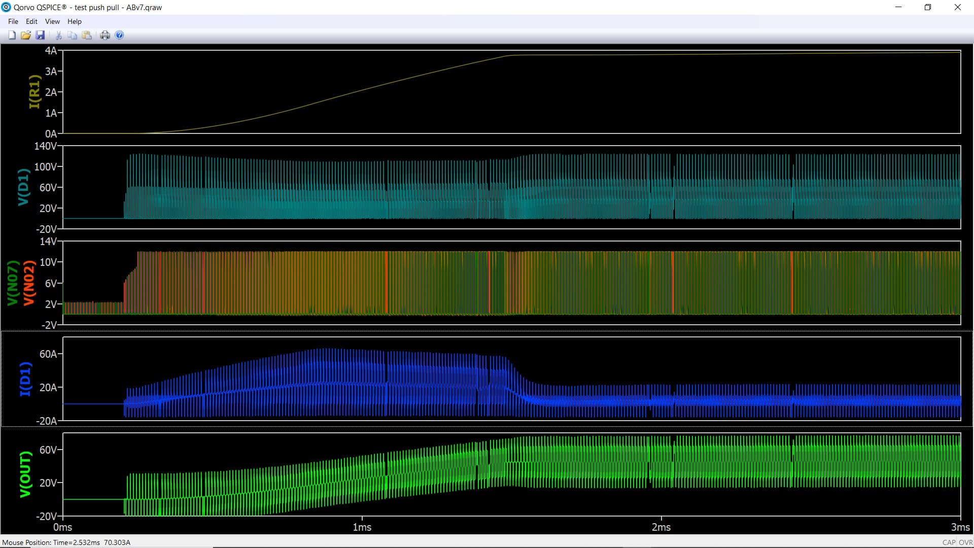
That’s how it should be. Take a closer look at what you and I have deduced. The signals are different and therefore the pictures are different. I was outputting signals relative to the floating earth - the voltage difference between the nodes. Pay attention to the 1 pF capacitor with its bypass resistor Rpar=1G.
My goal is for other people to be able to simulate this circuit. Do I need to send you the component library along with the file for a complete simulation?
I am using irfp150 MOSFET model in this circuit.
But you used a different model.
And you do as I do - use elements with embedded models. And you even try to use a separate model file for the diode. Put whatever transistors you want in your electronic circuits. But next time, if you don’t give me the model file again, then I won’t pay attention to your message.
I initially intended to upload the files, but unfortunately, due to the large number of models and the fact that it does not accept the zip format,I will send you the models one by one.
1N4746 18V.qsym (649 Bytes)
IRFP150N.qsym (1019 Bytes)
LM5030.qsym (5.0 KB)
PC817B-LTspice.qsym (1.8 KB)
TL431-Onsemi-BlockDiagram.qsym (2.5 KB)
TL431-Onsemi-Symbol.qsym (1.1 KB)
PC817A-LTspice.qsym (1.8 KB)
PC817C-LTspice.qsym (1.8 KB)
But unfortunately the format lib is not accepted.
I am confused how to send you lib the format.
library in general is text format, you just rename its extension from .lib to .txt and can upload to forum.
In general, I rename library to .txt and with .lib to link that in Qspice. It saves everyone time if to share in this forum. Embedded .subckt symbol is good way to eliminate the need of sharing a .qsch with library.
You don’t have to upload embedded .subckt symbol as subckt netlist is included in .qsch.
The problem is that, you have device in your schematic link to a .lib, and you didn’t share that and ask for support. After @bordodynov spent a lot of time help to review your circuit and make a working example, you update your request again.
You should either study his work to fix your, or upload everything at very beginning. Beware other is spending their own time in every support.
Unfortunately, my parts model is not complete.I don’t have a tl431-pc817B- or other model.
I thought that having the file format qsym lib The library is complete.That I thought wrong.
So I started finding some models on the internet.On this site I found some models
https://ltwiki.org/files/LTspiceIV/Vendor%20List/Diodes%20Incorporated/Spice/spicemodels_schottky_rectifiers.txt
But I don’t think these are optimized for qspise model
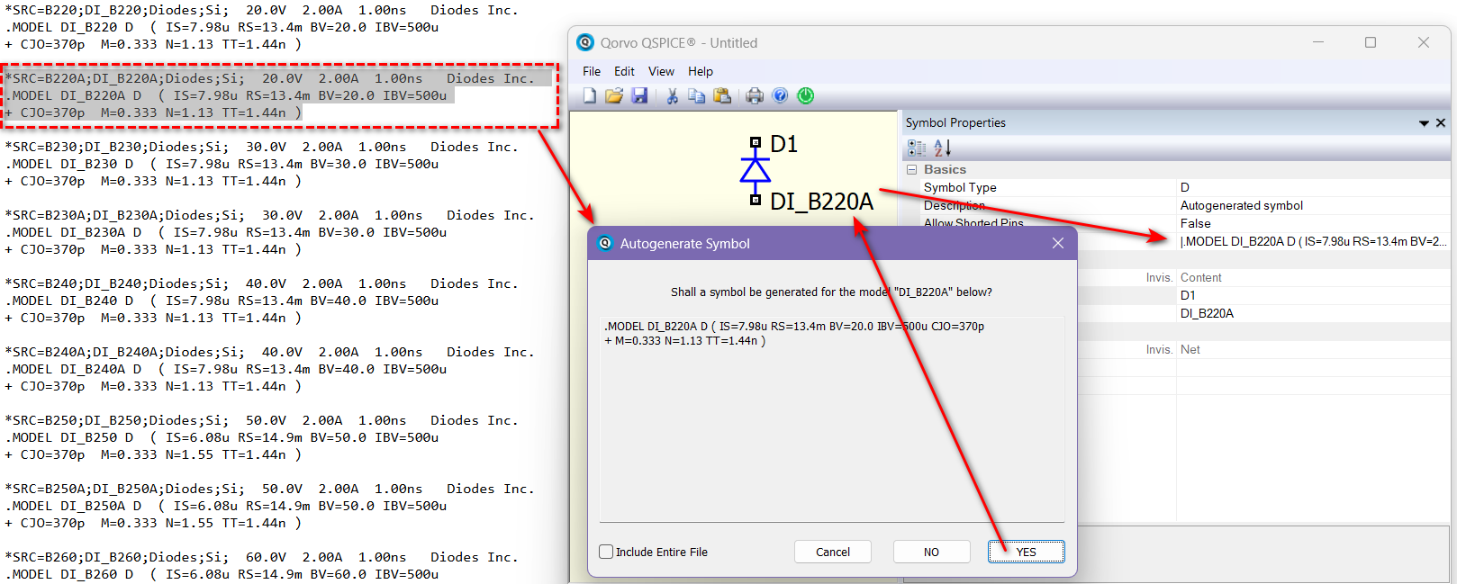
For example I downloaded a model from the above site.
*SRC=1N5819HW;DI_1N5819HW;Diodes;Si; 40.0V 1.00A 5.00ns Diodes Inc.
Schottky
.MODEL DI_1N5819HW D ( IS=191u RS=42.0m BV=40.0 IBV=1.00m
- CJO=239p M=0.333 N=1.70 TT=7.20n )
How to edit the codes for QSPISE model
Can this site be used for a library model?
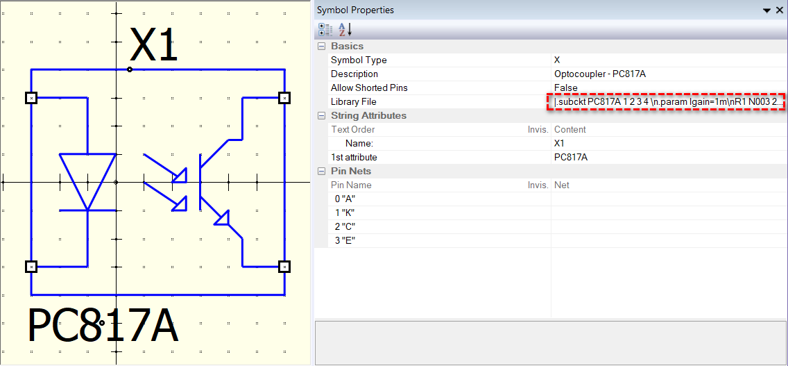
For symbols like “PC817A-LTspice.qsym,” they have their sub-circuit included in their Library File within their Symbol Properties. When you share a schematic (.qsch) with this type of symbol in it, you DO NOT need to share its symbol file (.qsym) separately, as this symbol contains the sub-circuit netlist. I refer to this type of symbol as an “embedded subckt symbol” because its sub-circuit netlist is embedded within the symbol.
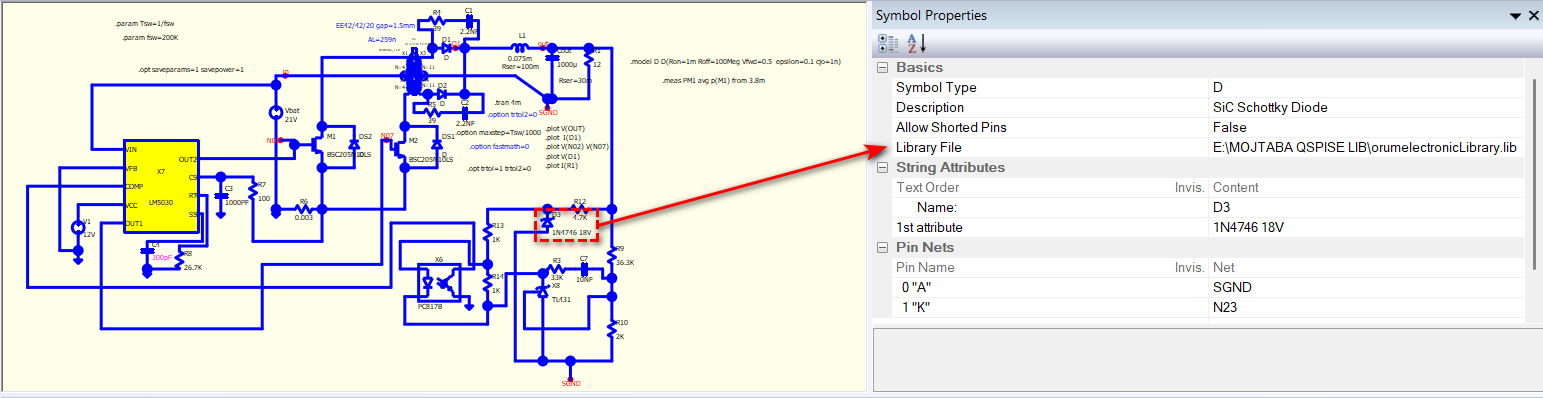
HOWEVER, for example, in your “test push-pull - ABv6.qsch,” you have a diode D3 that directly links to a library file in its Library File. If you share this schematic, you have to include this library file in the sharing. This is NOT an embedded symbol, and this symbol must link to that library to work in a simulation.
Additionally, using absolute file paths is NOT recommended for sharing schematics. Even if you share the library, anyone attempting to run your schematic will still have to rewrite the library path or create a folder with the same name to store the library file.
If you need to link to a library, you just need to have the library name. And for the path, suggests to use .libpath directive in schematic to tell where the path is. Or, add that path through “Symbols & IP Browser” to prevent using absolute path in your device.
You just need to copy and paste; the auto-generate symbol feature in Qspice will handle the rest to create an embedded symbol.
I suggest you watch the basic tutorial of Qspice (especially Importing 3rd Party Models into QSPICE) if you plan to work on such a complex level of schematics.
Your method is very good, but this method is good for one project.
Find it on the internet and add it to the project.
and cannot be used in the next project
I need a complete library of parts that can be selected in each project. Can’t I create groups of parts?
You can. My point is, if you need to send your schematic to a forum and ask for support, you have to pay attention to ensure that others can run your simulation without extra effort in back and forth asking your model and library and modifying your schematic such that can run in their own machine.
Hello, I need a current transformer for a previous project.
I studied this link.
And from the link below
https://disk.yandex.ru/d/71M79VuY5sOWew
I downloaded a model of the trans.
i need ct 1:100 To measure current push pull Converter
But this model requires L calculate
But I need a model that turns ratio of a transformer
TransF.qsym (1011 Bytes)
TRAN.txt (197 Bytes)
You shouldn’t be trying to use a model with a variable coupling coefficient. It is not for modeling a current transformer. Use a conventional single-turn transformer. This is a transformer on a ring with a secondary winding, and the primary is a straight wire passed through a ferrite ring.
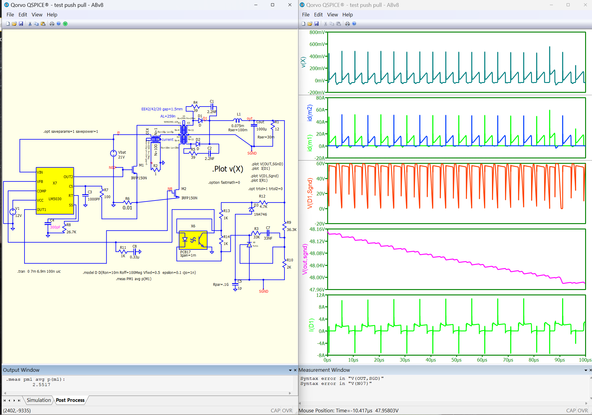
test push pull - ABv8.qsch (41.9 KB)
Thanks [bordodynov]
I have a few questions.
What are the parameters of the CT
Area=25µ Lm=25m gap=0?mU=2000 Fe=1Meg? Rs=10m Ls=20n ?
I want to connect the output off ct to the cs pin Of course, after rectification
I think the voltage at the point(vX) is too high Do you think it needs a filter?
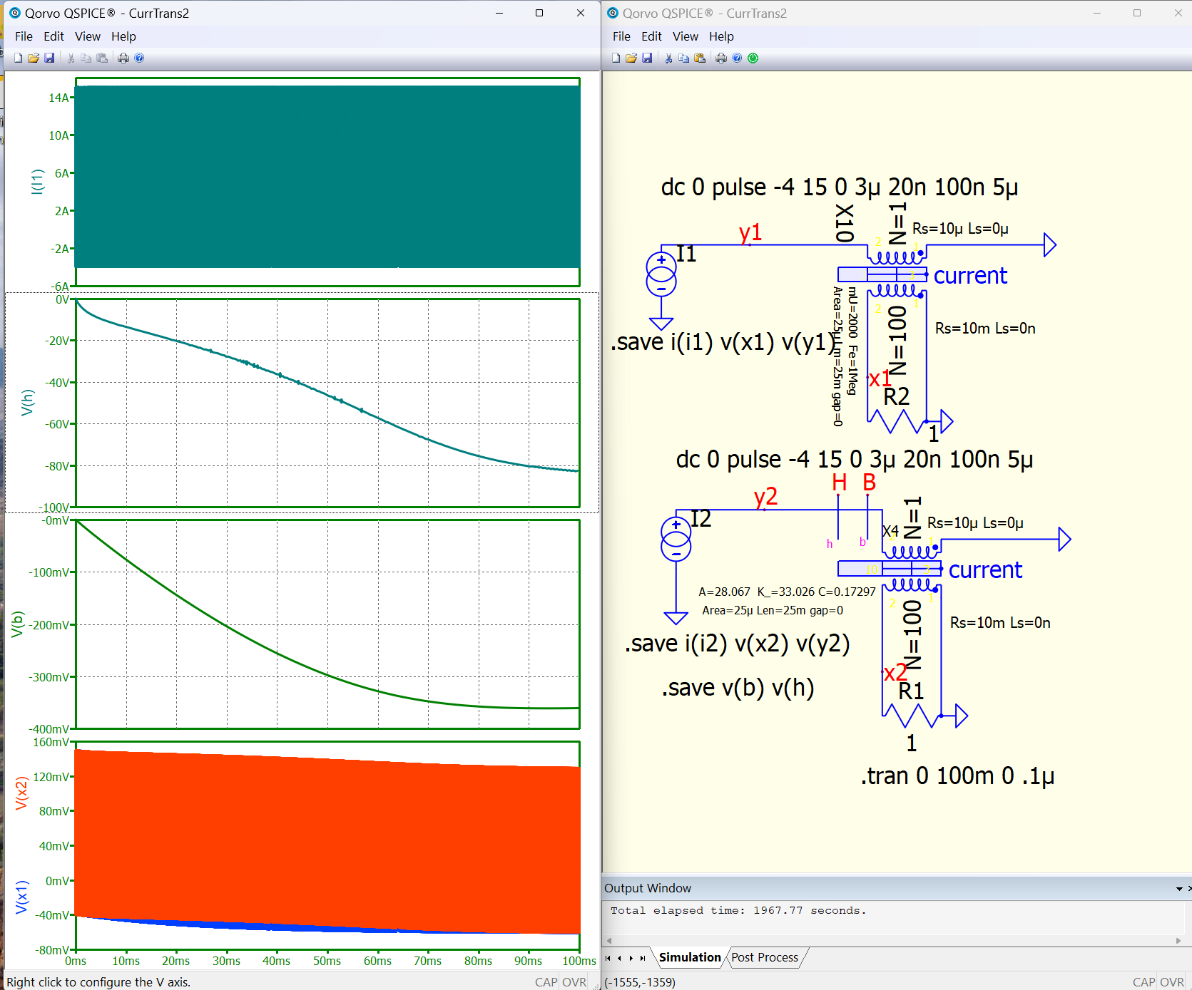
The transformer consists of three parts. Core: Area=25.e-6 is the cross-sectional area, Lm=25m is the length of the magnetic line, gap=0 is the gap, mU=2000 is relative magnetic permeability, Fe =1Meg is the boundary frequency of losses in the core.
Secondary winding parameters: Rs=10m is the resistance of the secondary winding, Ls=20n is the dissipation inductance of the secondary winding. With an output voltage of X=1V, the input voltage will be 10mV, but you can reduce the voltage by reducing the 1 ohm resistor.
Here I have shown that it is a bad idea to use a current transformer for a signal with a constant component. The transformer is entering saturation. In order to avoid this, it is necessary to take a large core and use the gap in it. The value of B (Tesla) has approached saturation. The second transformer has a ferrite core.
CurrTrans2.qsch (11.4 KB)
Thank you(bordodynov)
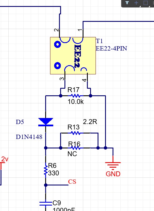
I used theEE22 core in the first model.
But then I used this model (LINE FILTER)
Does the filter line saturate?
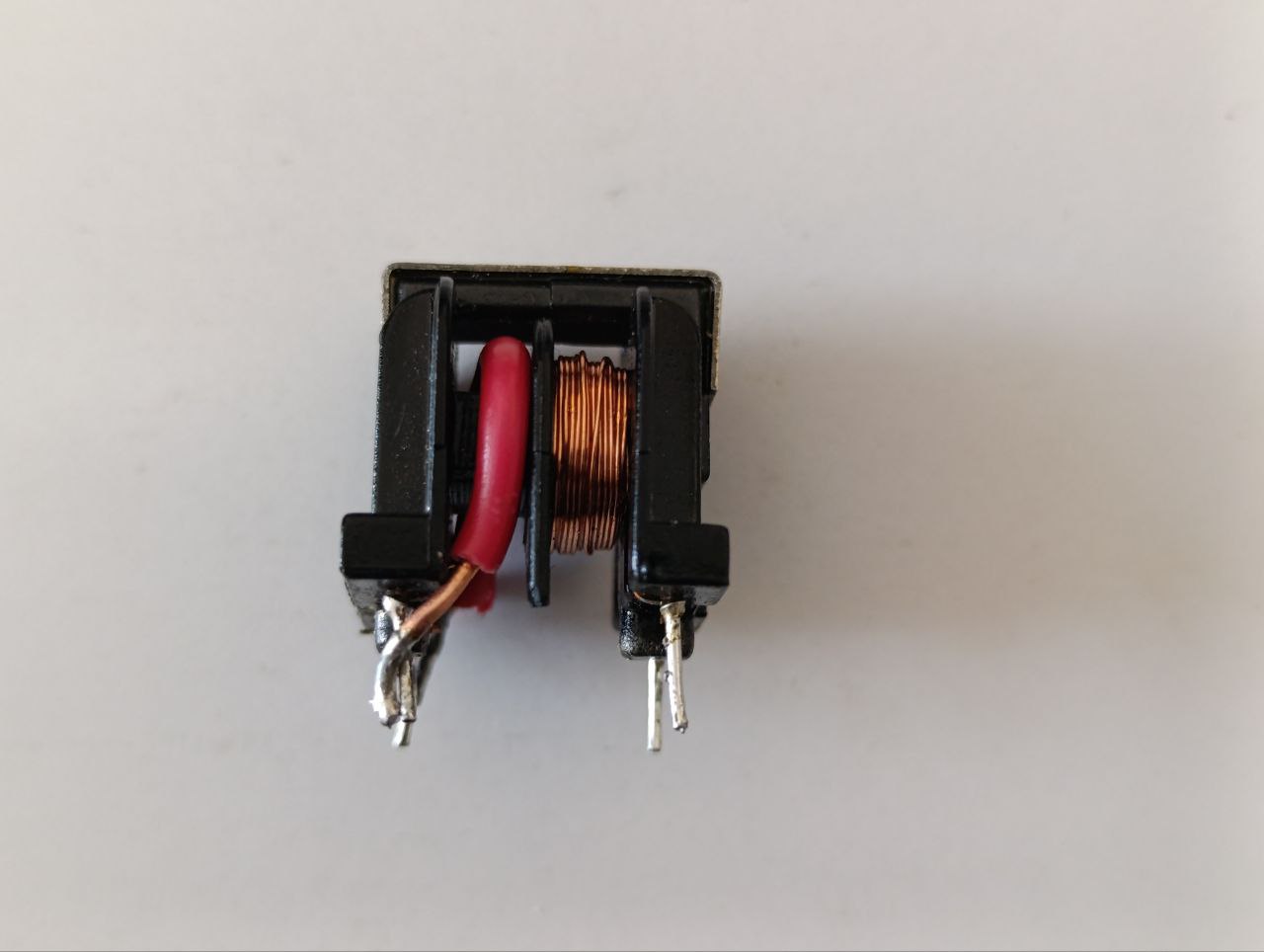
No, it won’t get enough, but it won’t be CT.