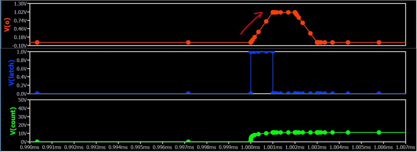
I’ve tried to use a B-source as a simple counter on rising edges only.
I’m probably missing something obvious.
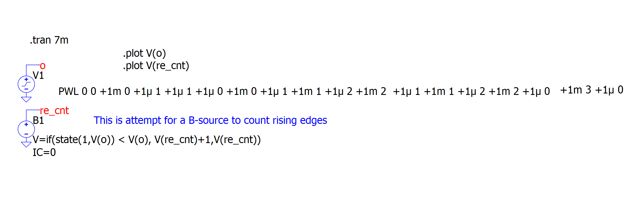
B-source_as_counter.qsch (2.2 KB)
The output is not what I expected.
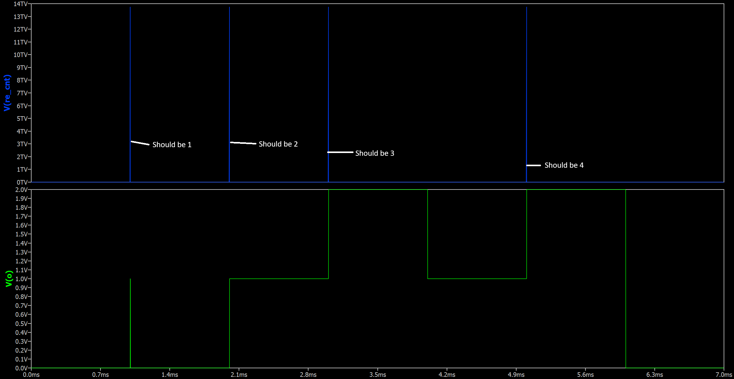
Any ideas?
Len
I’ve tried to use a B-source as a simple counter on rising edges only.
I’m probably missing something obvious.
The output is not what I expected.
Any ideas?
Len
Is your V(o) multilevel, rather than having simple 0 and 1 outputs? It is possible to use a B-source if your pattern is simple 0 and 1 (or two-level with a clear threshold).
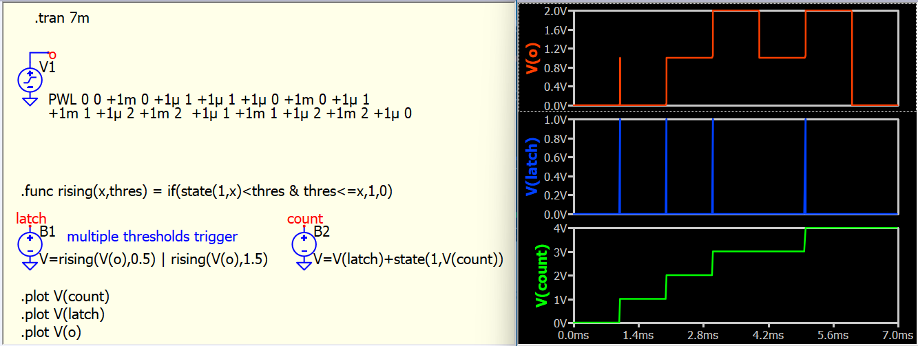
The problem is that V(o) rises over a duration, and there are multiple points that can latch during the rise, so the match will accumulate all of them. In general, we can set a threshold if it is just a two-level input signal, and ensure that the latch only happens once per rising edge.
Thank you. Truly excellent!
This was an academic exercise that I failed but you succeeded.
I had already created a C-Block function to achieve the same goal.
Out of curiosity, I was wondering if the same result could be achieved with standard QSpice components and not having to resort to C-Blocks.
The next big question: Which method (custom C-Block or 2 B-sources with .func) will yield the quickest sim time.
Len
FYI.
I change the “V=” statement in the B-source to:
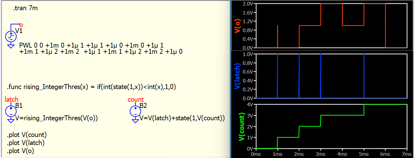
V=if(state(1,int(V(o))) < int(V(o)), V(re_cnt)+1,V(re_cnt))
It didn’t help. I figured placing a int() function on the Vo outputs would “digitize” the signal (causing a double to int conversion) hopefully causing threshold-like results. Apparently int() didn’t do the trick.
Oh yes, in your case, using int() will work better since you don’t need to keep track of multiple threshold values. The only requirement is that each level must be separated by at least 1V for a latch to occur.
I recommend keeping the latch action as an independent B-source (B1 in this example) and using another B-source (B2) to compute the result from the latch signal. Avoid combining them into a single formula. Each B-source creates an explicit voltage node that SPICE must solve; if the formulas are merged, the if condition logic loses its distinct node for solver. It is a bit tricky to explain, but I suggest following my advice. In general this is not requires, but Latch action is a bit tricky as it involve a state(n,x) memory action.
B-source_as_counter-KSK-2.qsch (2.9 KB)
Well, I don’t have a definitive answer for this one. A DLL might be slightly faster since it doesn’t introduce extra voltage nodes into the simulation. In theory, SPICE simulation speed depends on the node count, but I doubt the difference is noticeable in such a simple case.
However, there is a critical difference between using a DLL and a B-source: when an input changes, the B-source output updates at that same timestep, whereas the DLL output is delayed by one simulation step.
DLLs are generally easier to implement. With B-sources, you need to be familiar with the formula syntax, and most people find implementing discrete computation via B-sources quite dizzy.
You da Jedi Master of QSpice!
The use of int() helps in case the input rises by more than an integer value of 1.
Now for the question about execution speed (C-Block or B-sources): It appears from testing the C-Block has the quicker timing.
I created a schematic with both rising edge counters types. I disabled one type and ran it for 1Meg iterations. I then disabled the other type and enabled the first type and ran it for 1Meg iterations.
Results: C-Block => 1250 seconds. B-sources => 1510 seconds.
Not a big difference. I think you were right about the B-sources use another node voltage to calculate. Also, the equations in the .func and in the B-sources I assume are run-time interpreted. Whereas, the C-Block is design-time compiled.
I agree that the C-Block has a 1 timestep propagation delay. That is not a problem for my application.
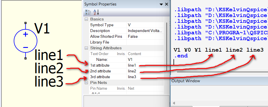
Another thing I learned from your example is that the attribute with the PWL definition can be broken by adding additional attributes to the V-source.
You did this because my PWL definition was way too long for one line. By adding additional attributes, you were able to effective create the appearance of line-feed. Nice trick!
However, using this trick you have to be careful of a few things.
Your observations are correct, and thanks for update the C-block and B-source comparison results.
Here is some additional information regarding string attributes: In Qspice, the schematic GUI always converts the schematic into a netlist. String attributes for any device (except the DLL block as you observed) are arranged sequentially according to their string order. While you cannot change this order directly in the schematic viewer, you can modify it within the symbol editor (if you create your own symbol).
Each attribute is separated by a space in translate the netlist. For V-sources specifically, because the syntax requires <voltage> first, items like PWL must come first, with other instance parameters following. View > Netlist is always your best friend if you are ever unsure what the underlying netlist looks like.
Vnnn N+ N- <voltage> [Additional Instance Parameters]
Hello Len
If you’ll search through the LTspice group’s archive (even posts, it’s possible it’s on the groups.io, rather than the backup from the Yaho groups, I don’t remember, it’s been a long while), you’ll find such an example from the unfortunately late analogspiceman. – Actually, I just remembered there’s an example on the ltwiki, see if it suits you.
Vlad