Hi. I’m a researcher (M.S course in University) and I want to ask some questions about DWM1001 module. I’m using 4 Anchors and 1 Tag in Outdoor environment and comparing UWB 3d(xyz) position data with GNSS data.
MY question is : Is there a linear interpolation function in DWM1001 module?
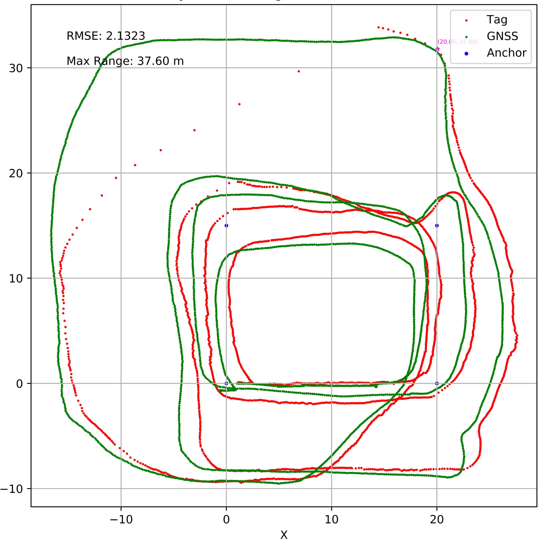
The picture I took to this forum is the data of GNSS & UWB Tag position. but there are some points which are seriously different with GNSS data. I did 200+ experiments, but all results shows like, After the area of disable-to-range, it just interpolate with current position to last position(right before the current position).
for me personally, it doesn’t really look like an inaccuracy in measurement but more like an issue with your overall positioning, as the Y axis values seem to fit pretty nicely and the whole X axis is shifted to the right.
Could this maybe be caused by your coordinate systems not matching? I don’t know your system in particular, but from my understanding, you’d need to somehow get the coordinates of your GNSS and UWB to align. This looks to work pretty good on y, but not on the x axis
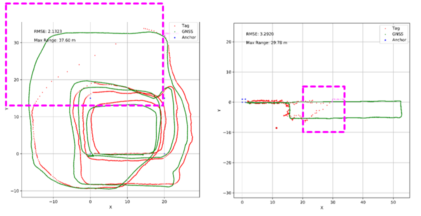
Thank you for your reply. There can be a little bit offset between GNSS & UWB Cordinates. The image I show you above could confuse you so I take a 1 graph more below! I want ask about the “pink box” I draw in graph, the area I think linear interpolation task occurred. As you can see, there are red points far from the GNSS data which have huge difference in position value and my opinion is that this difference is not just offset or noise data, but it is the result of the interpolation processor. In the right graph which has pretty well matched coordinates, it contains the data out of the trajectory(GNSS).
Do you use the provided software that comes with the DWM1001-DEV board? I personally never used it, so I don’t know whether thats the coordinate system provided by the software. If there is any interpolation or averaging going on, it’s happening inside the software, not on the chip itself.
From my experience, your assumption could be correct tho, as the locations you get are quite good for raw results.
If you could tell me what software you are running, it would be quite helpful.
I use ROS(Robot-Operate-System) packages from github (dwm1001_ros/src/dwm1001_main.py at master · 20chix/dwm1001_ros · GitHub ). But this package as I analyzed just use API command in python code(dwm1001_apicommands.py). I think this package just publish the position data without any processing.
It looks like the areas you marked are significantly outside the area defined by the anchors. In addition to the longer ranges involved you are going to have a poor GDoP (geometric dilution of precision). Any ranging errors or dropouts are going to have a far more significant impact on the positioning accuracy in this situation.
What the impact of these errors is depends on exactly how the positioning system is attempting to deal with the issues. Since it’s a black box it’s hard to be sure. As Fhilb indicated, it is in the firmware supplied rather than the UWB device itself, that firmware is closed source and so it’s hard to know exactly what it’s doing…
What exactly are you trying to research? It may be more beneficial to instead get the measured ranges from the system and then implement your own position calculation system, this would give you significantly more control over how bad / missing data is handled. I’ve found a least squares approach in python using the numpy.optimise libraries to be both simple (maybe 25 lines of code) and effective for calculating positions. It was slow but it worked well.
I believe even the raw range outputs of the system have a small amount of averaging going on. Normally this only acts to reduce measurement noise but it could have some impact if measurements are intermittent or you are traveling rapidly in comparison to the measurement rate.
It is of course possible to avoid all of this and obtain raw unaveraged, unfiltered ranges where you know exactly what processing is going on if you write your own firmware but that is probably way beyond your project scope or timescales.
The TAG is outside of the anchor defined area. Even this is a TWR system so it also works outside of the anchor defined area is is always better to have the TN inside. It is pretty nice visible on your test - once it is inside it returns a good values, once it is outside you getting worse and worse values. The GDoP affect it a lot. There no mechanis that is trying to pervent this - except the manual where is written that you should move in the area between anchors (at least it should be there).
The usable DWM1001C range with PANS firmware is about 25m and at certain direction you can get much more. However I typically say that it is 20-25m but in you test setup you go much further so you done get all 4 measurements bu tonly 3 and Im wandering that you are able to get position even at upper left corner which is a quite far from anchors.
In general the pink area is quite out of RF range / installation recommendation so if you want to improve it you need to add more anchors.