OK, Len, I should let @KSKelvin answer this as I might reveal my ignorance…
If I understand correctly, this error is thrown when QSpice cannot find a timestep where the voltage(s) differ. It starts out with longer timesteps and reduces them until it finds a difference. If you say, “stop trying when the timestep is less than X,” QSpice would stop reducing timesteps earlier than otherwise and will simply abort earlier, right?
Could be entirely wrong of course.
I’m assuming that you’ve already tried 80-bit math and aren’t messing with timesteps in the DLL, of course.
Simulation software uses numerical methods to solve circuit equations. Numerical methods solve these equations iteratively — starting with an initial guess, computing a result, and repeating the process until the error falls within specified limits.
In transient analysis, if an acceptable result cannot be calculated at the current timestep, the simulator reduces the timestep and retries. Multiple options control this behavior; for example, .option itl4 sets the maximum number of iterations allowed per timestep. If the simulator still cannot reach a satisfactory solution (meaning the result does not converge), it eventually returns a “timestep too small” error. This happens because the simulator keeps shrinking the timestep down to its minimum limit without finding a convergent solution that meets the error criteria.
In short, you cannot set a custom minimum timestep in SPICE; reducing the timestep is an automatic internal mechanism for solving circuit equations numerically.
Traditionally, a switching circuit is the most challenging circuit for SPICE to resolve (i.e., stiff I-V characteristics).
I also used to hope if mintimestep option can be added, or if Mike may consider to allow the simulator to step over the error and instead send a warning on the console that the solver has decided to skip timestep too small error and continue.
Regarding the 80-bit mode, in my work (SMPS) I generally try to avoid it, since good realistic components parasitics and clever .opt can improve the circuit stability with less compute time penalty.
Anyway, can you share your .tran .opt settings you use currently?
Lastly, on the Cblock, have you consider adding a small Rout and Cout parameters?
But the conept is that SPICE looks for a solution at a timestep and it fail, so, it move to a smaller timestep and keep repeating but eventually timestep is too small but still cannot get a correct solution. So, how it possible to skip an incorrect solution as reducing timestep was to find the solution.
I maybe wrong, but I believe Multisim have such algorithm logic… The logical reasoning is, perhaps the circuit can be self correcting in the next few timestep so trying to skip over such problematic timestep maybe self resolving.
Though, of course Multisim can often be problematic
KSKelvin described well what SPICE does and, if you only have digital parts, I would check for race conditions. The “timestep too small” errors are a plague that has been going on since the original SPICE, ~50 years ago, and likely won’t stop at QSPICE. It might help to add some capacitance in key nodes, and maybe even to relax the timestep/ttol (being too strict about transitions can also incur the wrath of the solver).
I can’t say for QSPICE but, in LTspice, adding Rser, Cpar to the stiff voltage sources could also solve the glitch (though I noticed QSPICE is more permissive about this); or even use current sources with a parallel resistor (BI might work slightly better). Something to consider, at least.
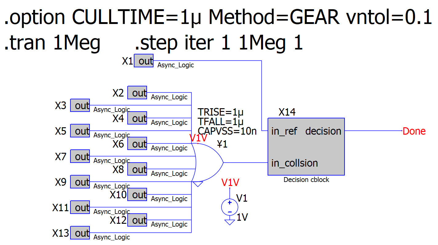
The Async_Logic CBlocks are just that… logic with asynchronous timing relative to each other. The Decision_CBlock makes a logic decision and publishes the output.
Originally, the 12-input OR gate did not have TRISE, TFALL or CAPVSS attributes set. I first added TRISE, TFALL to the minimum time quanta I’m using (1us). The timestep error still occurred.
I added CAPVSS=1n. It appears to postpone the timestep error to a latter iteration. Good!
When I change CAPVSS=10n, it appears to further postpone the timestep error to an even later iteration. Better.
Here’s some further info to your inquiries:
I am using MaxExtTimeStep() in the CBlocks to predict when the block needs to process the next event.
I do not use Trunc().
I use ForKeeps testing since the CBlocks don’t need to compute intermediate timestep values.
I’ve used Method=Trap and I’ve used Method=Gear. No improvement.
I’ve used Fast Math and “Slow” math. No improvement.
Any more thoughts? Thank you in advance.
PS: Right now, since I can execute a number of steps before the error occurs, I’m incrementally collecting the data up to the error. As you can imagine, this is not optimal and is laborious.
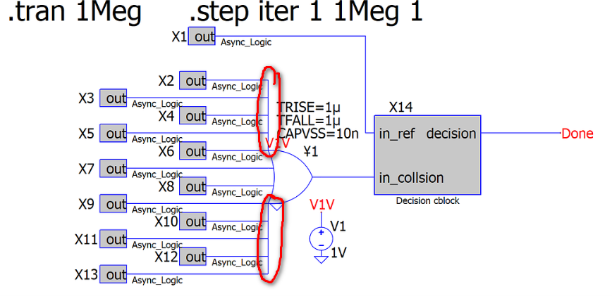
What is happening here? Initially, I thought you connected multiple outputs (X2, X3, X4, X5, X6) into a one of the input of a 4-input OR gate, but I cannot see a connection dot between X2, X3, X4, and X5 on the wire. What is your purpose here? Or what is the relationship among all the DLL outputs? Is there any chance you accidentally connected multiple DLL outputs together?
I would assume if the many Blocks shorted together into OR gate because you simply don’t have any OR gate with enough input ports.
Anyway, I have one instance where I don’t put any maxstep in .tran and the sim goes timestep too small, and the problem disappear as I add some maxstep (like 2x the max Tsw).
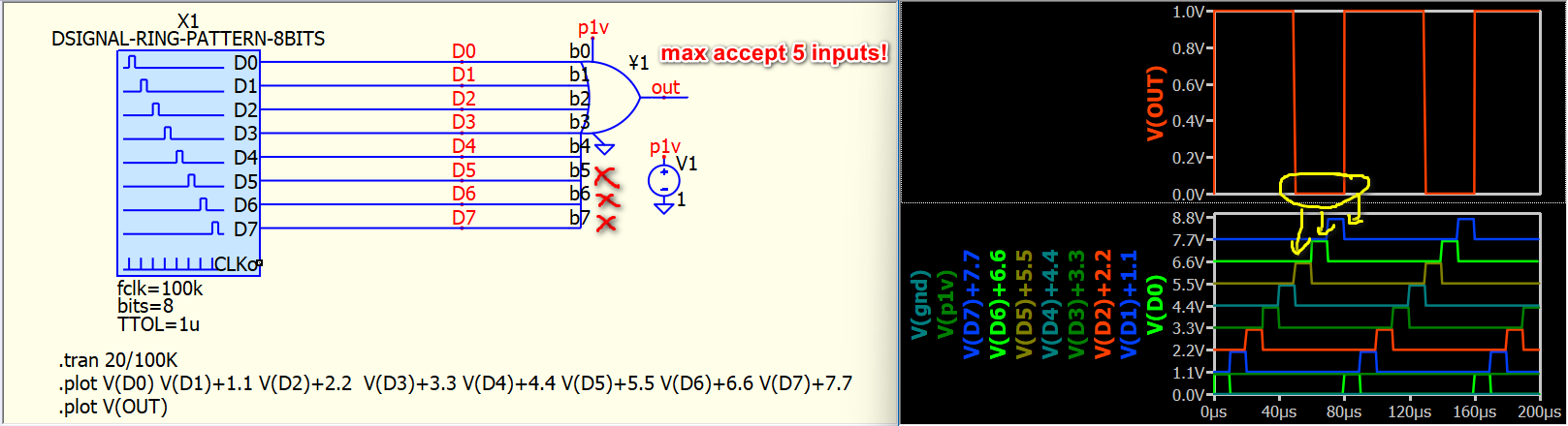
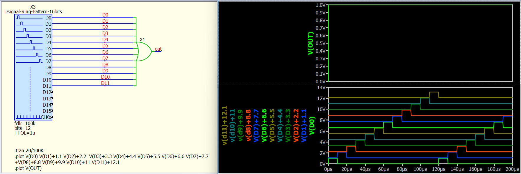
I guess you created a custom symbol with 12 inputs? BUT, for an OR gate, you can only build up to 5 inputs! I think Mike didn’t write AND, OR, and XOR gates to support more than 5 inputs.
Without any settings, there is a possible race condition (let’s assume) and that is because, out of all the transitions, two or more can collide within the timestep error window. You don’t know when or where. Now, if you add CAPVSS to all, then all of the transitions will follow the same pattern, since (I doubt?) you have set any transition to have more leeway than the others (AKA all for one and one for all). So, nothing will be changed, except that the engine will have a slightly smoother transition (for all) and the chances to detect the collision increases a bit. More precisely, if dV/dt=inf without caps, with them it will be dictated by the caps but, still high (limited by pulse widths).
So, you’d be better off not using the lazy approach and, instead, add one here, one there, and observe. Yes, it’s tedious, yes, you don’t even know whether it is a race condition, or not. The lazy approach will not solve much, as you saw (mostly luck).
Actually, it might be worth setting up the supplies with a random extra bit (e.g. 5+random()/100. They don’t even need to be all, try a few first. Since they’re not time-varying they will hardly encumber the matrix, even if you have extra nodes. With this, Rser, Cpar will probably not be needed. Adding some randomness to your I/O in the code would also do but, having it in the schematic will make it clearer where it is and who is affected. Just a few thoughts.
However, I just noticed, are you running your .tran simulation for 1 million seconds? That is 277.78 hours… it seems very unrealistic to me. We generally have to limit maxstep to 10 times less than the lowest switching frequency in the design, as by default maxstep is Tmax/1024, in your case, maxstep is 16mins, represent you possibly have one simulation step apart by 16 mins… But you definitely simulating a switching circuit, so, how SPICE suppose to coirrect work in this time scale or a very dynamic time step?
Well… since we normally don’t have many different options for the mathematical formula for a certain feature, I have no idea about speed vs different math formula. Just beware of the delay() function; it can slow things down. In the past, people used delay() to delay a switching signal, but it is definitely not a good option, as I discussed in the DelayedPulseTrain post recently.
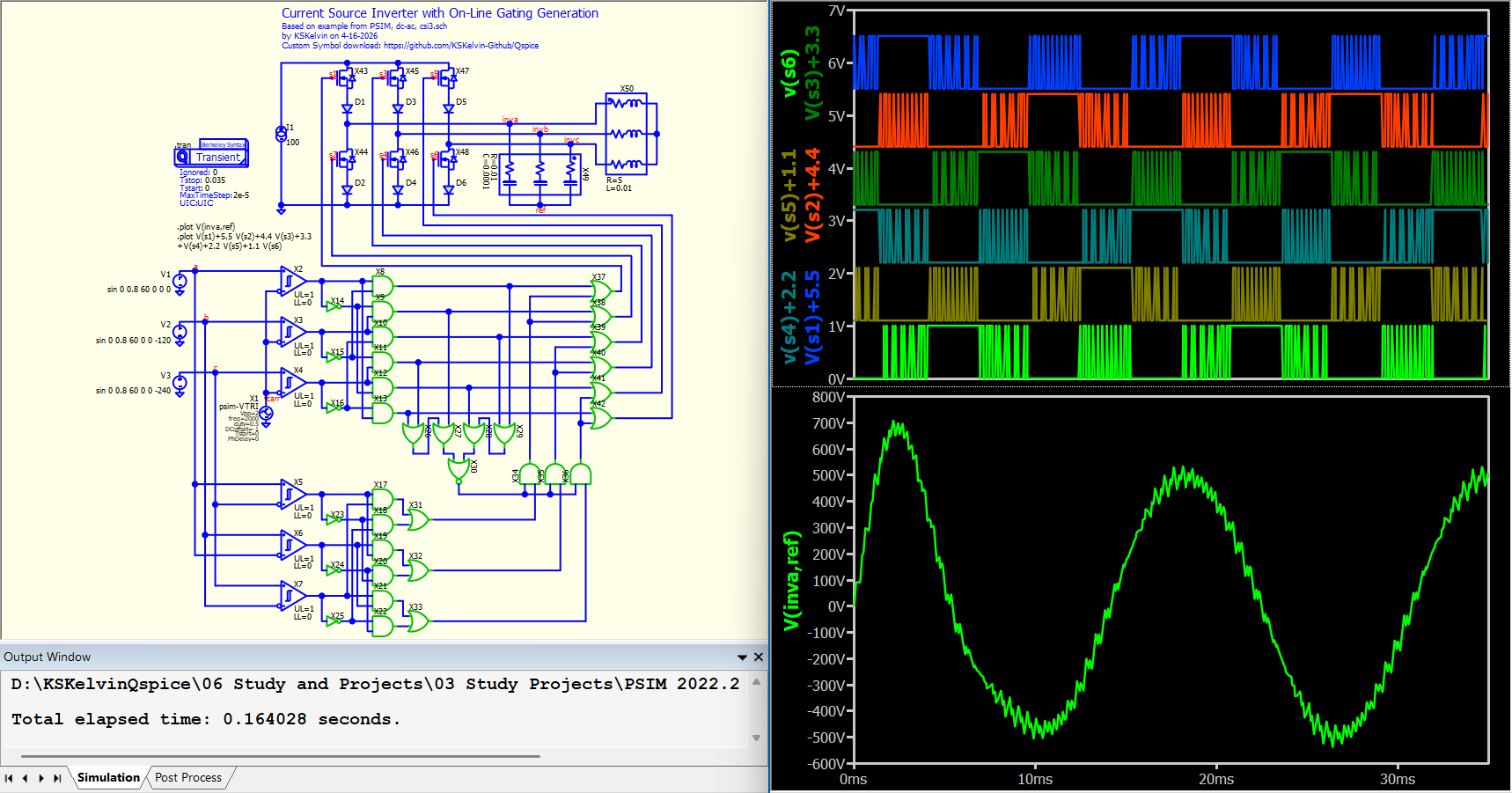
A B-source is the traditional way to implement logic; if you refer to TI PSPICE models, all logic uses B-sources. But since PSPICE doesn’t have a memory function, and B-source logic has a stiff I-V curve, the result is that simulation speed dramatically decreases. However, with PSPICE, they don’t have another option.
I built a B-source logic library because sometimes, if you don’t want to use many ¥-devices, a B-source is a very friendly option. Also, a B-source solves the logic at the same timestep, unlike a ¥-device (DLL-based), which requires a one-timestep delay between input and output. However, B-source don’t have TTOL, so, it won’t reduce timestep at approaching a switching action.
I replicated a PSIM example, and this one has the highest number of separate gates in a single simulation from what I built. Everything works quite well. I changed the outline of my B-source logic to green so that I can recognize them easily.
That’s smart approach. So, the ttol is strictly only rely on the PWM comparator, then all the B-source logic just do the magicall at the exact timestep (which won’t waste extra tiny steps)
I think I should also add these logic gate into my library… Thanks for the idea
Right, a major downside of ¥-devices one-simulation-step delay is that if you have multiple layers of logic, you have to consider delay matching to yield the correct logic; otherwise, a one-simulation-step glitch (an unexpected HIGH or LOW output) can occur. I don’t have to consider one-simulation-step delay matching with B-source logic. In theory, B-source logic may trigger timestep too small issue more easily, especially if there is logic that output feedback to its input, like D-flop. I have to add a delay using state(n,x) function for D-flop B-source version.
The 12-input OR gate is a special symbol I made. It makes use of the all the inputs allowed in the ‘¥’ device. The extra pins for the inputs are ON the graphic line. That’s why there are no dots. The Async_Logic CBlock outputs are NOT shorted together.
Special note: If I disable the OR gate and short the “in_collision” input to GND. No Timestep errors.
Personally, when QSpice fails with the TimeStep Error. It reports the time at which it occurs. However, it would be very nice if it also listed the node where the failure occurred. This would reduce debugging time to identify the subcircuits at issue.

 this also my first option if timestep too small is returned.