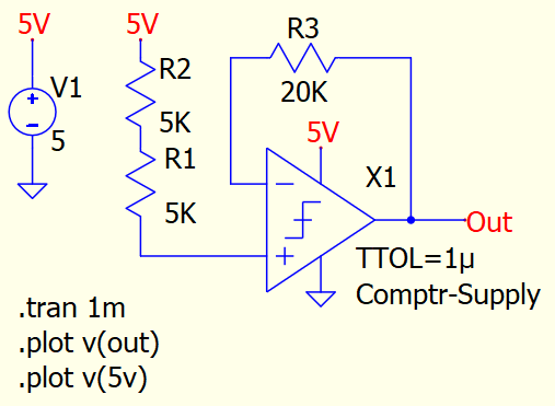
For some reason this circuit does not work anymore in latest updates. Voltage at V1 source and output node are incorrect. Circuit works if there is one resistor in input side but not with two in series. Jumpering R1 or R2 results correct behavior. I have stripped down everything unnecessary from original comparator oscillator circuit. Ideal comparator in circuit is from Kskelvin’s lib and contains one B-source and ¥-Device as OR gate.
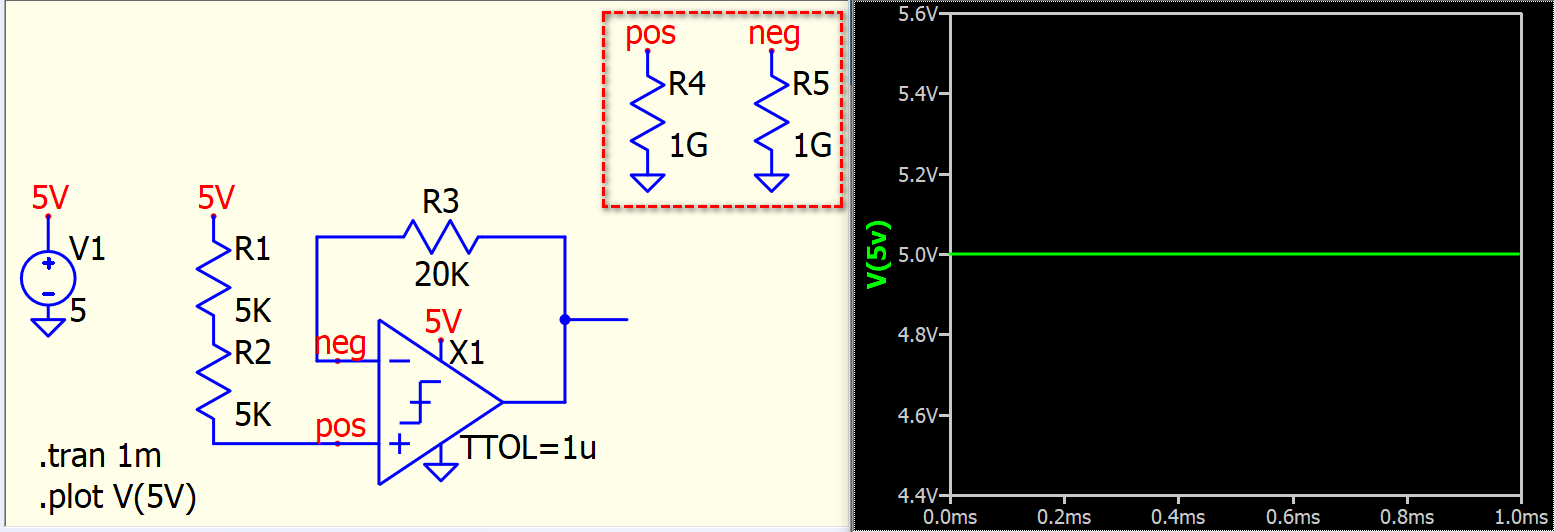
Based on your input, I am considering whether I need to add input impedance to the ideal comparator symbol. If you were to add, for example, a 1G resistor at the positive and negative terminals in your original schematic, would you still obtain the same result as before?
Original circuit is still malfunctioning. Add one resistor to example and it fails again.
Anyhow, I dont think you need to modify the comparator. It used to work just fine in older versions. If you can’t trust ideal voltage source holding its value, you can’t trust anything.
Well… I sent this to Mike for review because it fails to calculate V(5V) as 5V starting from the 12-Dec-2024 version.
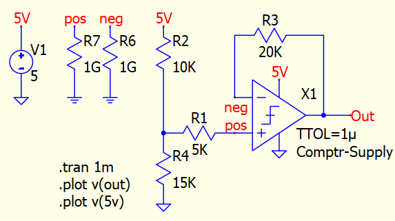
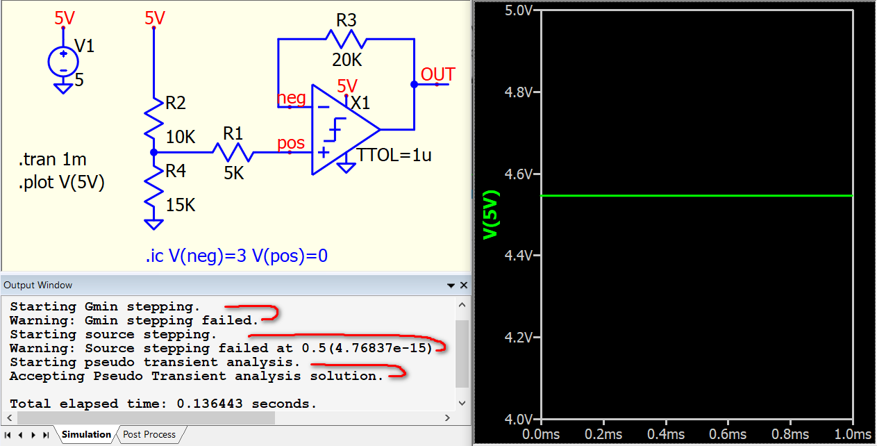
However, this setup seems a bit strange to me. The issue seems to lie in the DC solution. When you examine this circuit, what do you expect the DC solution to be? Should V(OUT) be 5V or 0V?
Given:
V(pos) = 3V
if V(neg) = 0V, V(pos) > V(neg), and V(out) should be 5V. This will immediately force V(neg) to 5V.
When V(neg) = 5V, V(pos) < V(neg), and V(out) should be 0V. This will immediately force V(neg) to 0V.
Therefore, the DC solution cannot be determined.
You can add ‘uic’ into .tran, for example, .tran 1m uic, to skip the DC solution. However, V(out) will need to flip its state in every simulation step. But as you mentioned, this is just a part of the circuit. Perhaps your original circuit is more reasonable.
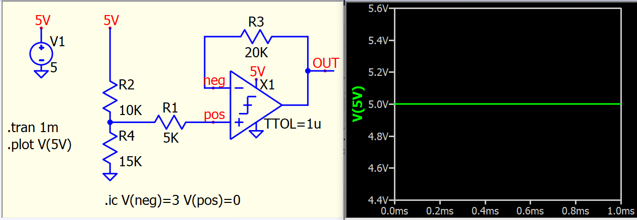
For example, if we specify an initial condition for V(pos) and V(neg), we can prevent this circuit from encountering difficulty in resolving the DC solution and produce a correct DC result.
For your information, in the output window, it indicates that Direct Newton iteration, Gmin Stepping, and Source Stepping all failed to find a DC solution without .ic or uic. It eventually resorts to a Pseudo Transient analysis solution and provides an incorrect V(5V). Anyhow, this circuit has been copied to Mike for review, but we typically need to be very cautious with oscillation circuits, especially this setup is unrealistic if without any delay in the comparator.
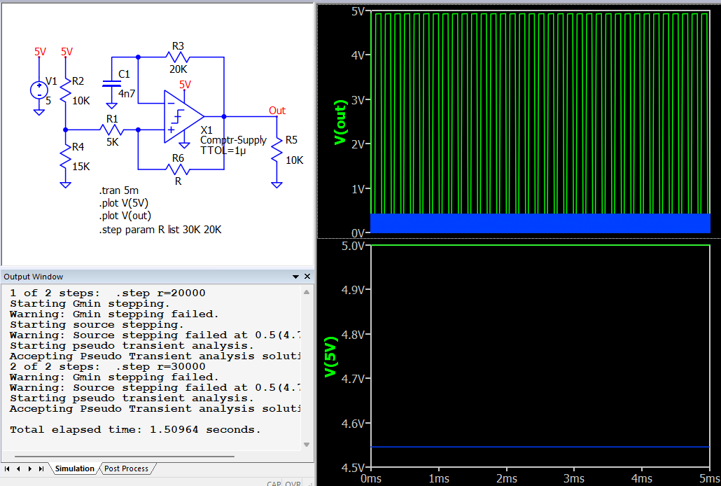
Here is circuit that actually does something. I managed to find way to get correct and wrong result with stepping. Correct result is close enough compared to real comparator model. Circuit is still an example, but now oscillation is limited to reasonable RC. Still it fails to find DC solution. I don’t have old version to check if it was the case before. UIC also solves the original circuit. I did not realize try it as I got back to old simulation that used to work fine.
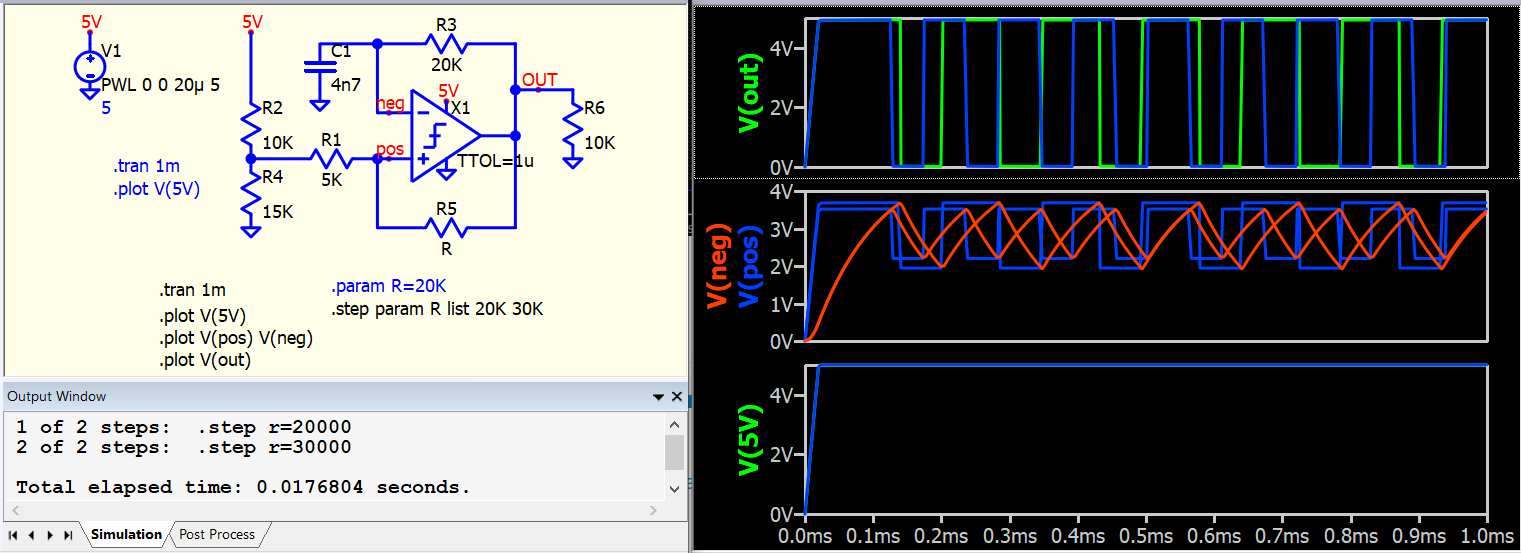
You can also solve this circuit with a ramp source to prevent problems in solving the DC solution for an oscillation circuit. Will provide an update if Mike’s review this. However, my suggestion is to define initial conditions for the oscillation circuit (with UIC, .ic or PWL supply source), or you are presenting an unnecessary challenge for the simulator.
A pure voltage source would have infinite current capability. Not typically found in logic circuits.
Some default impedance should be assigned to voltage sources if the circuit is supposed to work under realistic circumstances.
The difference between science and engineering is delivery times and price.