I’m using three DWM3000 as Anchors & one as Tag. So the scenario is, anchors are places at the measured distance from each other, assuming one anchor at the origin. I’m fetching the ToF from the anchors to the tag using TWR, and by using the formula I’m acheiving distance between the anchors and tag. After that, I’m applying 3d trilateration to acheive the coordinates of the Tag.
Issues, I’m facing are that distances are changing abruptly however the anchors as well as the tag are fixed at a position, secondly my tag and the anchors are in the xy plane still there is a large value of z coordinate at the Tag.
Is there any solution related to these issues?
How much are the distances changing? I will typically see range measurement noise in the 3-5 cm region. A small amount of averaging or other filtering helps reduce this significantly.
There will also be an angle dependency, if you rotate the antenna you will see an impact on range. This could be up to 15 cm.
There are also signal level and temperature effects that are in the 5-10 cm region but they shouldn’t be changing rapidly.
If that doesn’t explain it then look at the environment, is anything changing? People or other objects moving around will impact the results if they block the direct path.
As for the Z value, if you want a 3d solution then all the anchors in a plane is a bad situation, you have no way to distinguish which side of the plane you are on. However with 3 anchors they will always form a plane. So your options are either add more anchors or move them so that you can hard code the side (e.g. put the anchors up high and say the tag is always below them).
How well calibrated are your antenna delays? If everything is in a plane and the ranges are slightly long due to antenna delay or some other constant bias then the solution will have have a Z value. It will also have a slight X/Y error depending on how big the bias and how far from the middle the tag is.
First of all, thank you @AndyA for the response.
I have already checked and verified the starting three points, you mentioned above and they’re encountered efficiently. The point about the antennas delay, while starting with it I have calibrated it and checked it, but still i’ll recheck that point.
But @AndyA, I didn’t fully get this thing,
“As for the Z value, if you want a 3d solution then all the anchors in a plane is a bad situation, you have no way to distinguish which side of the plane you are on. However with 3 anchors they will always form a plane. So your options are either add more anchors or move them so that you can hard code the side (e.g. put the anchors up high and say the tag is always below them).”, you mentioned above. Can you please elaborate it a little more?
The issue I’m facing is exactly the same you described in the end, “solution will have have a Z value. It will also have a slight X/Y error”, but I didn’t get the last sentence with it, this one, “depending on how big the bias and how far from the middle the tag is.”.
If the tag is equal distance from both anchors with the correct measurement then it’s in the middle of the line between the anchors. If both measurements are the same but are both longer than half the distance between the anchors then the solution would still place the tag halfway between them but also above or below the line connecting them.
But what if the tag wasn’t in the middle? If the tag was at one anchor then the solution would work out as being not just above the line between the anchors but also past the end of it.
So the most obvious impact of a constant bias on range measurements is a Z error. The larger the bias the larger the Z error. But it also depends on geometry, the further the tag is from an anchor the smaller the height error needed to compensate for the range error.
Unless everything is symmetrical the range errors will also result horizontal position errors. These will normally be smaller, the more asymmetric the ranges (or the range errors) are the larger the horizontal errors will be.
This all just comes from the maths of the position calculation. There isn’t much you can do about it other than calibrate out the errors as best you can and/or add more anchors and find a best fit to the over determined solution.
Our approach has been to do a lot of calibration and then use 12 anchors in the position calibration. But it also makes the system a lot more complex.
Hey @AndyA, hope you’re doing fine.
I have rechecked the antennas calibration delay, they are responding fine.
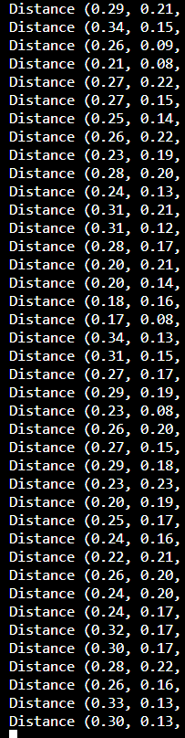
But when I have implemented the conditon you’ve mentioned before of two anchors with a middle tag. So, I kept the two anchors 46cm apart from each other, and the tag in the middle of them i.e. at 23cm. I’ve received the output attached.
Both of your anchors have exactly the same antenna delays? That seems very unlikely.
Ignoring the noise the averages of those ranges are different. If things are giving different average values when at the same distance with the same configuration then you clearly have a bias in the system somewhere. Normally I’d expect that to be antenna delay or antenna orientation. You can eliminate antenna orientation by putting the two anchors close to each other (keep them 15-20 cm apart) and oriented the same way. That way the antenna angles to/from the tag will be very similar for both.
Also I’d increase the distance to the tag significantly. Signal levels will have an impact on measured range. Signal level is related to the inverse square of the distance. So at short distances a small difference can result in a relatively large change in signal strength. If you can get things further apart then the variation in signal level is smaller and so any correction for this effect is less critical.
Every anchor and every tag will have a different antenna delay, for accurate results you need to calibrate every single unit individually. This is (in theory) easy once you have a single correctly calibrated unit, getting that unit can be tricky.
You can put 3 units in an equilateral triangle, ideally in the middle of a large open area, ideally at a reasonable distance from each other (10-15 meters). You can then measure all of the ranges between them and calculate the antenna delays for all 3 units that will reduce all the range errors to zero. Since the ranges are all the same the signal levels should be the same which means you don’t need to worry about the accuracy of your signal power compensation when doing it this way.
You can eliminate antenna orientation by putting the two anchors close to each other (keep them 15-20 cm apart) and oriented the same way. That way the antenna angles to/from the tag will be very similar for both.
& in your next reply you suggested,
You can put 3 units in an equilateral triangle, ideally in the middle of a large open area, ideally at a reasonable distance from each other (10-15 meters).
I’m confused in these statements, like what will be the best way to opt for the best results? Can you please elaborate this so that the point is cleared?
They are two different solutions for two different issues.
If you want to verify the cause of the differences (orientation or antenna delay) then you put the two anchors next to each other so they have the same orientation with respect to the tag.
If you want to calibrate delays you want everything as symmetrical as possible. So in a triangle with the antennas all facing into the middle so every single measurement is over the same distance and hitting the antenna 30 degrees off centre. That may not be ideal but it is then the same for everything.