Improper argument to .tran can cause problems - and "thumbs up" icon feature

I’ve fallen into the habit of expressing the transient command as “.tran 1” in some simple simulations. It seemed to be harmless, but under some conditions it can give very bad results. I’ve attached a demonstration file that shows the problem. Running a .tran of 1 displays a 24Hz waveform, while running a .tran of 100m gives a 1khz waveform. Mike suggested that I was not using the .tran correctly, suggesting “It has no good way to determine the step size. Use .tran 0 1000m 0 1µ”.

While entering the corrected .tran command, I noticed a new feature of the “thumbs up” icon as I was entering the .tran. I hadn’t seen that before, so I asked Mike if there was any documentation about it. He responded with “I really don’t see documenting “thumbs up” as required. BTW, I think it only shows up if you type a space character after a command that can be parsed. It doesn’t check if the command is correct.“

If you set .tran 1 without mentioning what the maxstep should be, the target maxstep is approximately 1/1000 (i.e., Tstop/1000).

The target maxstep may vary depending on different devices. Without seeing your file, I’m unsure about your setup. However, you can run into issues if you simply ignore whether a simulation should include a maxstep. It is user responsibility to determine maxstep, if you know how SPICE works.

Problem with minimal tran arguments.qsch (1.8 KB)

Here is the file in case you want to see how this lazy habit got me into trouble. I would rather have a warning or an absolute refusal to run if there was not enough information to accurately run the .tran command. Guessing and assuming may work for a while, but a bad assumption hidden down at the bottom of a simulation could waste a lot of time.

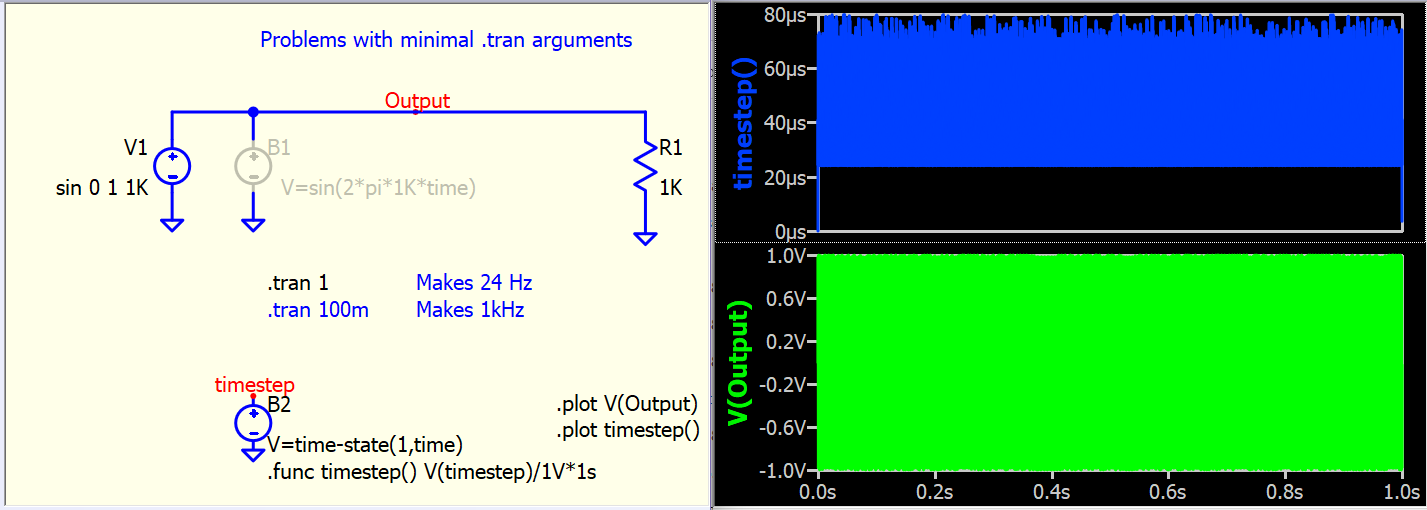
What you are observing is called aliasing, which can occur even when using a digital oscilloscope with a sampling frequency lower than the signal frequency. If you do not make the correct judgment in setting the timebase (or sampling rate) of an oscilloscope, you will waste a lot of time and obtain useless data. This situation can arise in real-life measurements as well as simulations.
https://www.tek.com/en/support/faqs/what-aliasing-and-how-do-i-detect-it-and-fix-it-my-oscilloscope

Let me try to explain what is happening in SPICE. When you input a sine voltage source, it produces a “correct” waveform. This is because the sine voltage source can adjust the maxstep based on your input frequency, and the timestep changes between 20us to 80us which maxstep at around 80us.

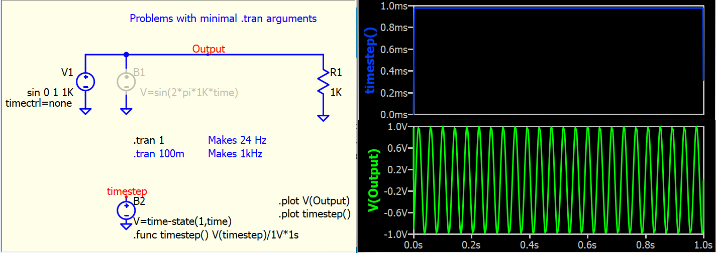
However, Qspice can set the proper maxstep because it has a timestep control scheme in some native devices. Here, I have added an instance parameter to V1, which is timectrl=none (to disable timestep control in this Vsource). Now, as you can see, the maxstep is set to approximately Tstop/1000 (i.e., 1/1000=1ms in this case). This clearly indicates an undersampling condition if there is no algorithm or directive specifying the maxstep. It is important to note that undersampling is not necessarily incorrect; there are systems (e.g. some digitial filter algorithm) that can work with undersampling. However, in simulation, it is advisable to avoid this situation.

Now, for the final question: why does your setup only provide a maxstep of 1ms?
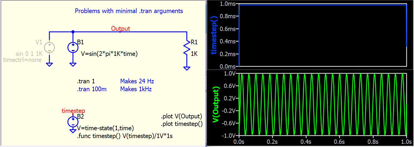
You have placed the formula sin(2*pi*1K*time) in B-source. In SPICE implementation, B-source does not have a timestep control scheme. Therefore, it simply takes the suggested maxstep from .tran in this scenario. Since B-source can have any kind of formula, there is no way a maxstep can be tell effective from a formula. (In your case, it seems easy… but you have to know you can put any formula. For example, if I put V=if(V(x)>1,1,0) into B-source, what timestep can be recommended?). Thus, it becomes the user’s primary responsibility to assign the maxstep.

Consider this scenario: if I were to give you a signal in the real world, how would you determine the sampling rate of your oscilloscope? You would not blame your oscilloscope for not automatically providing you with the proper timestep for measuring a signal. It is the user’s responsibility to figure this out.

In conclusion, the thumbs up is only to check your syntax, similar to compiling code without errors. This does not necessarily mean that your code can run meaningful results.

Timestep control is crucial in SPICE simulations. This is essential for balancing accuracy and simulation speed, and it is particularly important when simulating switching circuits.

Here is my study note of timestep control in Qspice in Github.
Qspice - How Time Step Works.pdf

1 Like

Yes, this is an aliasing issue. My whining complaint is that QSPICE is deciding to use some timestep that is not obvious. One of my runs actually changed the unknown timestep value part way through the simulation, drastically changing the data-sample rate and the displayed information. Without strange waveform displays, I get no feedback indicating that I may be having a problem. Many of the current digital oscilloscopes will detect aliasing problems and provide display indications of the problem. At least, if I were forced to supply this input, I would be thinking about what to expect. When it is automagically filled in for me, I’m fat, dumb, and happy as I continue my work with bad data. I’ve learned my lesson and I’ll always wait until (at least) I get the thumbs up icon.
Thanks,
Carl

In your example, there is nothing wrong with using 1ms as the max step. If I plan to simulate an undersampling system, it is not necessary to run with a smaller time step as it will only make the simulation time longer.

Once you are aware of the nature of SPICE simulation, I don’t think it will be a problem anymore.