Brubo3
June 17, 2024, 6:26pm
1
Hi all,
I was trying to import an inductor model from CoilCraft’s Model Libraries for LTSpice Zip folder:Model libraries for LTspice® | Coilcraft
Then found the series of inductor, XGL4020, opened the document and copy and pasted the code associated with XGL4020-102 freq. (Pasted Below)
*======================================================================
SPICE Model generated by Coilcraft
Coilcraft Part Number : XGL4020-102
Inductance = 1uH
Model Parameters:
Valid Frequency Range = 0.1MHz-80MHz
Ambient Temperature = 25 degC
Inductor Frequency Model
Use model for Frequency Domain simulations
R1=33.7
R2=0.0082
C= {Cpar}
K1=0.000001
K2=0.236
K3= {Ind}
K4=0.009
K5=0.004
L=9.093E-07
Is=18.6392
a=0.7005
L_Z0=0
L_EL=0
L_F0=0E6
PkZ=1271.07114
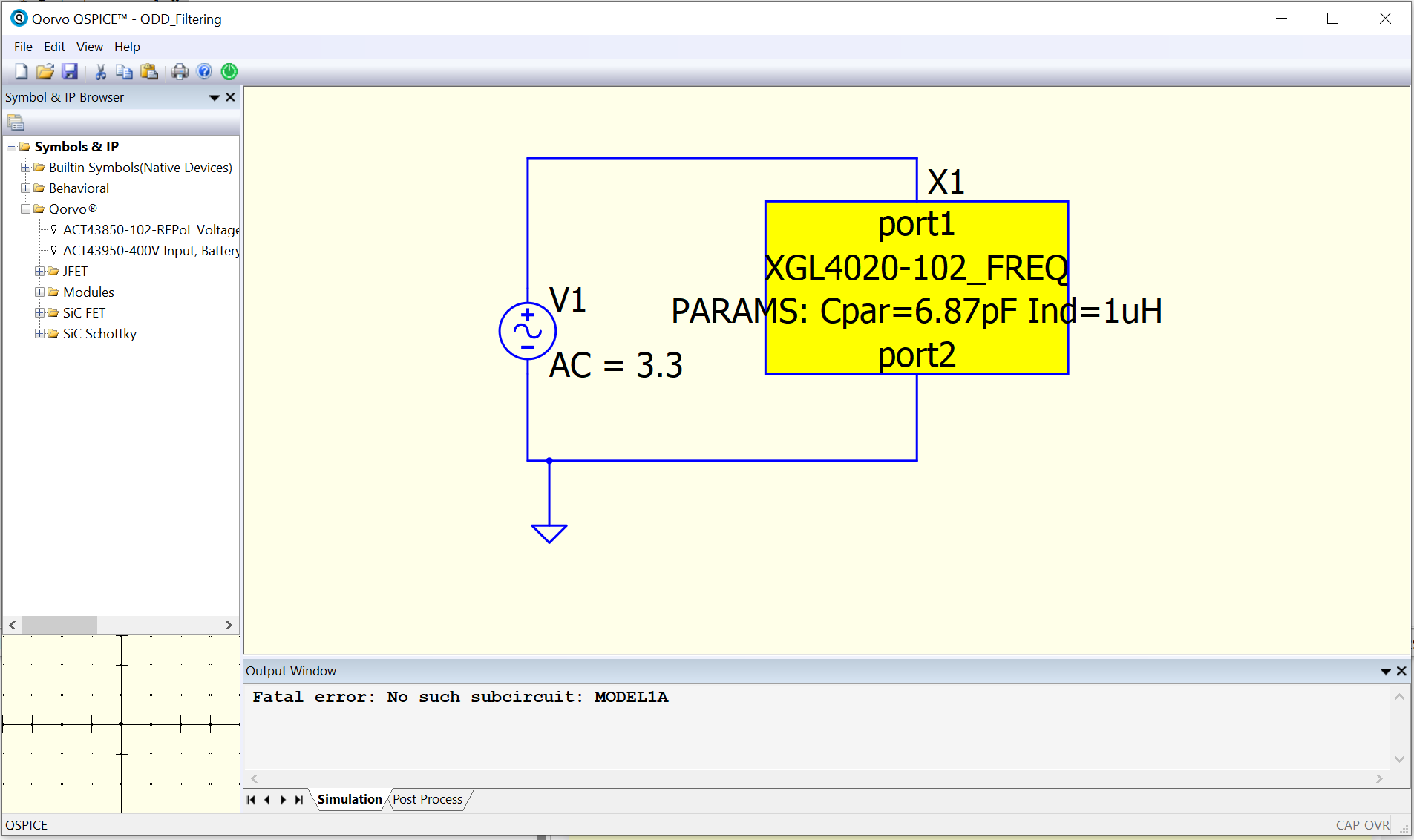
The Error I see on my end:
I tried following the advice with other posts, but this component still seems to not work from what I am doing. Any help would be greatly appreciated.
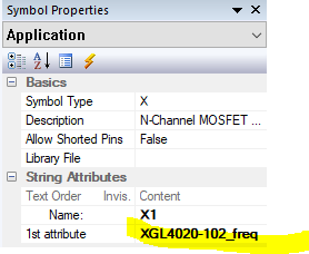
Brubo3:
XGL4020-102_freq
It seems that you are not calling X1 by it’s subcircuit name: XGL4020-102_freq but instead you have MODEL1A as it’s subcircuit name, thus it doesn’t work. Update the name of X1 to be XGL4020-102_freq:
Brubo3
June 17, 2024, 6:59pm
3
Hi SuplexPowerSlam,
I got the name changed, but the error still pops up with just Model1A.
I’d remove “X1 port1 port2 Model1A PARAMS” from your sub circuit definition. That seems to be conflicting with the statement directly above it, “XGL4020-102_freq port1 port2 PARAMS:”
In other words, try this subcircuit:
.subckt XGL4020-102_freq port1 port2 PARAMS: Cpar=6.87pF Ind=1uH

R1=33.7
R2=0.0082
C= {Cpar}
K1=0.000001
K2=0.236
K3= {Ind}
K4=0.009
K5=0.004
L=9.093E-07
Is=18.6392
a=0.7005
L_Z0=0
L_EL=0
L_F0=0E6
PkZ=1271.07114
.ends XGL4020-102_freq
Brubo3
June 18, 2024, 12:16am
5
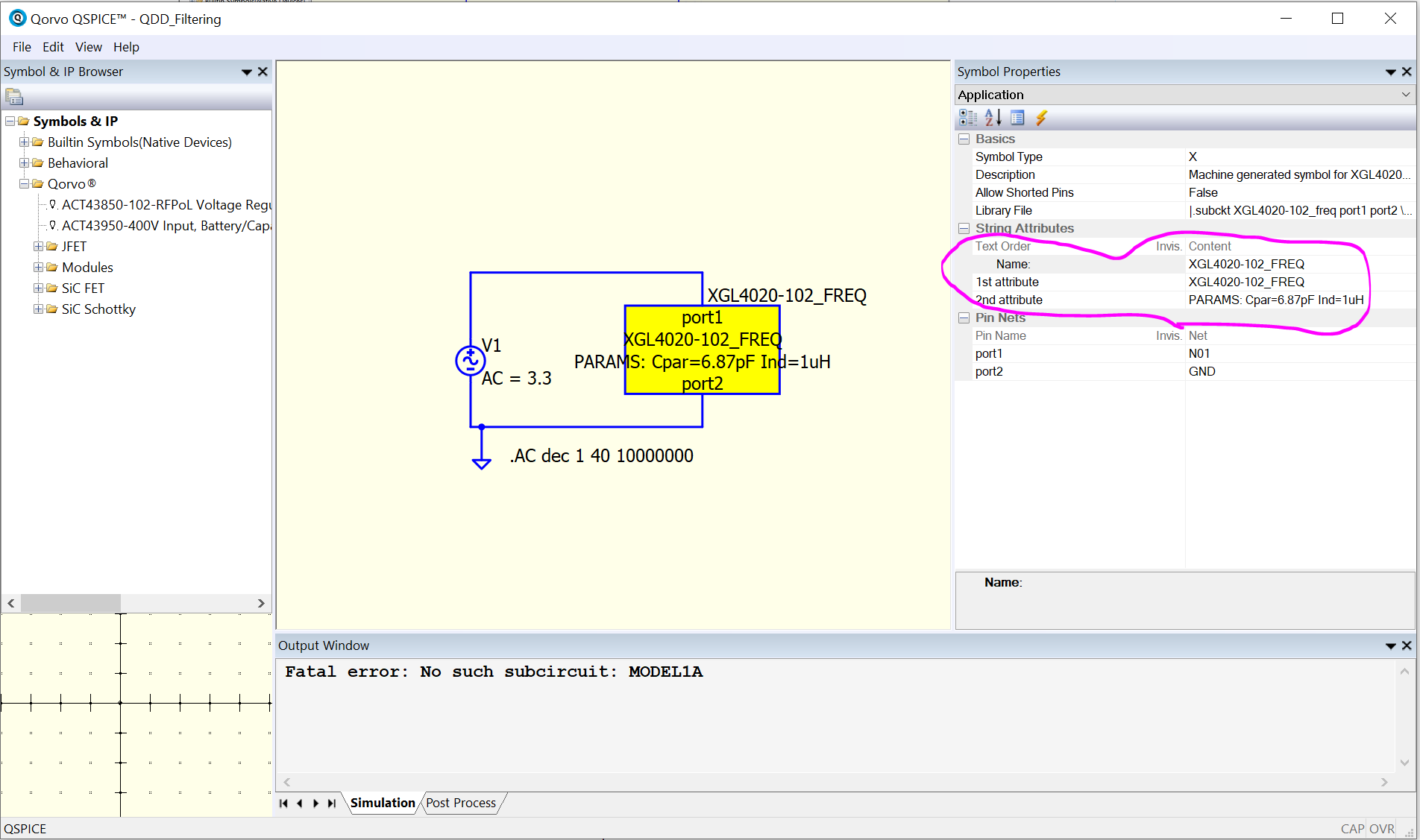
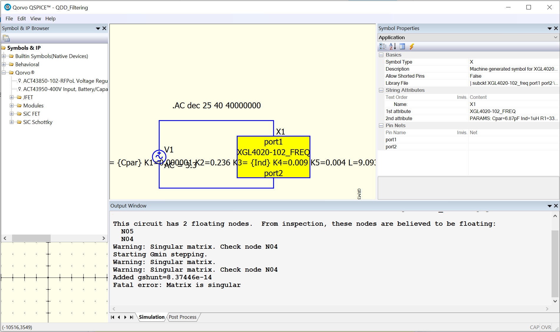
Tried using the subcircuit you provided gives me a new node error
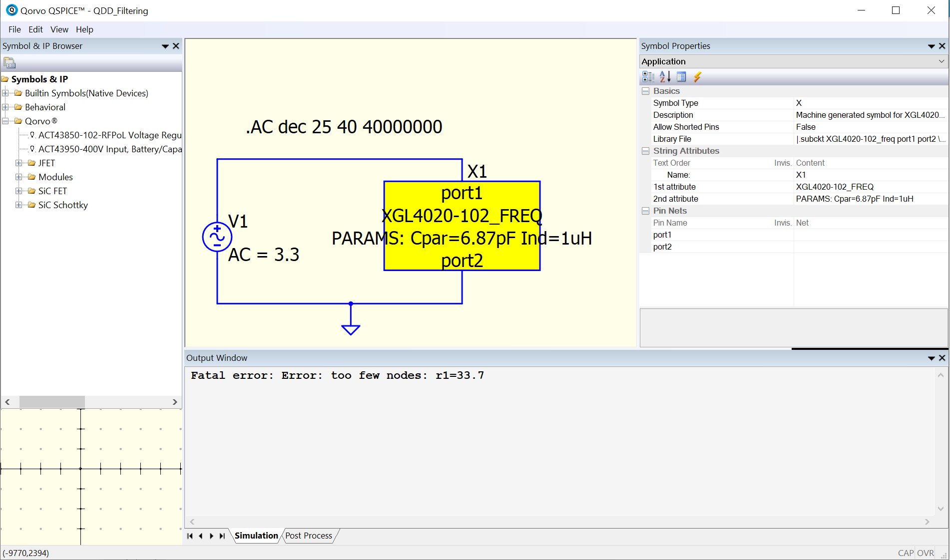
Then I tried removing the line from the subcircuit model in the original document, with it now popping up with a new error.
.subckt XGL4020-102_freq port1 port2 PARAMS: Cpar=6.87pF Ind=1uH
R1=33.7
R2=0.0082
C= {Cpar}
K1=0.000001
K2=0.236
K3= {Ind}
K4=0.009
K5=0.004
L=9.093E-07
Is=18.6392
a=0.7005
L_Z0=0
L_EL=0
L_F0=0E6
PkZ=1271.07114
New error image on next post->
Do you have a ground (shortcut : G) in your circuit?
Brubo3
June 18, 2024, 4:28pm
8
unfortunately, nothing has changed on my end
ivan1
June 18, 2024, 7:49pm
9
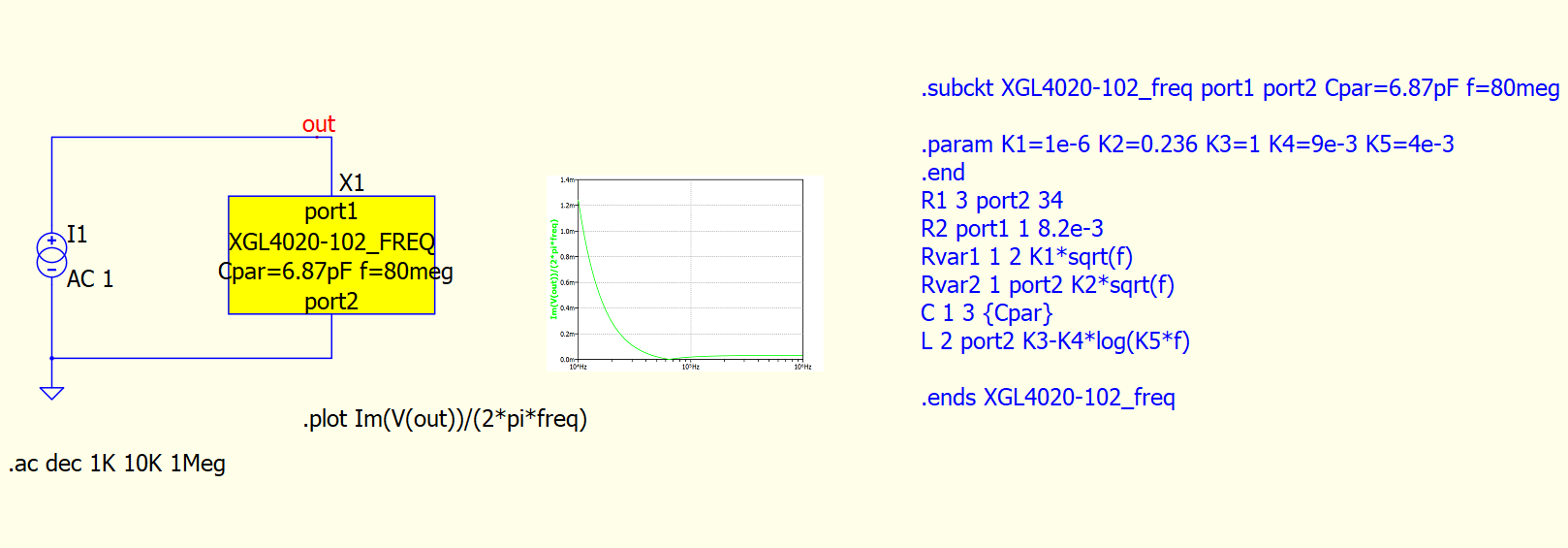
inductor.qsch (3.9 MB)
Here you have inductor model like in pdf.
1 Like
Brubo3
June 18, 2024, 8:15pm
10
Thank you for going out of the way to make this component!
Best,
How can we change the symbol from the generic rectangle to a inductor one?
I browsed the properties and I see “machine generated…” and the ‘types’ do not seem to change the symbol visually in the schematic canvas.
TIA
ivan1
June 24, 2024, 7:45pm
12
Here is the symbol for inductor.
inductor.qsch (3.9 MB)
Also check this tutorial.
Best regards
1 Like
Thanks!
I’ll see the video when I get some quality time!
Again thank you for all support.
I have a General Reference Guide you can download from my Github which explain the procedure from a .subckt into a .qsym (user symbol), which is in this guideline, section Part 2B, Symbol for Subckt [Embedded Subckt]
Qspice/Guideline/Qspice - General Reference Guide by KSKelvin.pdf at main · KSKelvin-Github/Qspice · GitHub
I took @ivan1 schematic and created a symbol which looks exactly the same as Qspice standard inductor. Here is your reference.
Parent.XGL4020-102.qsch (2.4 KB)XGL4020-102.qsym (746 Bytes)
1 Like