Hi All,
I am making a PCMC simulation,
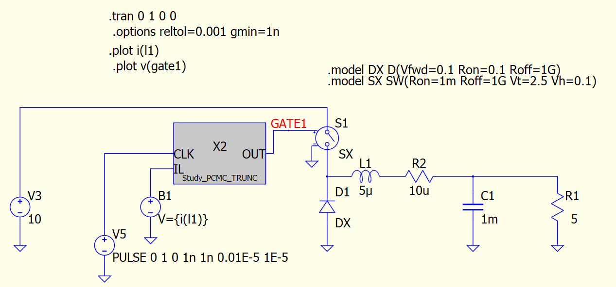
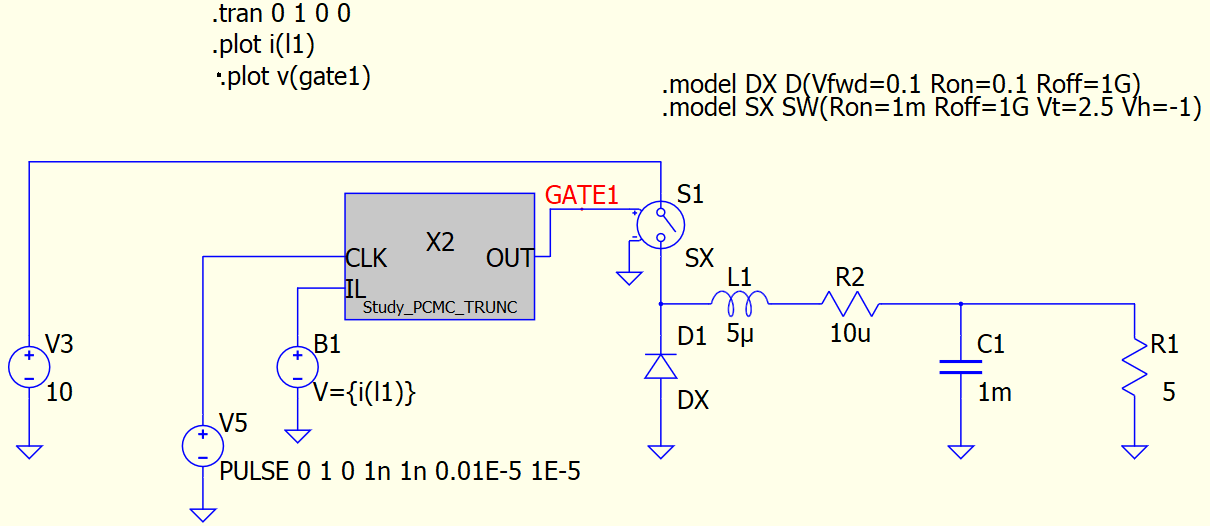
The actual PCMC is implemented in C-code with fixed current reference set at 1A to turn off the SWITCH.
// Automatically generated C++ file on Thu Oct 19 16:11:47 2023
//
// To build with Digital Mars C++ Compiler:
//
//    dmc -mn -WD study_pcmc.cpp kernel32.lib

union uData
{
   bool b;
   char c;
   unsigned char uc;
   short s;
   unsigned short us;
   int i;
   unsigned int ui;
   float f;
   double d;
   long long int i64;
   unsigned long long int ui64;
   char *str;
   unsigned char *bytes;
};

// int DllMain() must exist and return 1 for a process to load the .DLL
// See https://docs.microsoft.com/en-us/windows/win32/dlls/dllmain for more information.
int __stdcall DllMain(void *module, unsigned int reason, void *reserved) { return 1; }

// #undef pin names lest they collide with names in any header file(s) you might include.
#undef CLK
#undef OUT
#undef IL

double pwm;
double clk_prev;

extern "C" __declspec(dllexport) void study_pcmc(void **opaque, double t, union uData *data)
{
   double  CLK = data[0].d; // input
   double  IL  = data[1].d; // input
   double &OUT = data[2].d; // output

// Implement module evaluation code here:
   if((clk_prev<=0.5)&&(CLK>=0.5))
   {
      pwm = 5;
   }
   if(IL>1)
   {
      pwm = 0;
   }
   clk_prev = CLK;
   OUT = pwm;
}
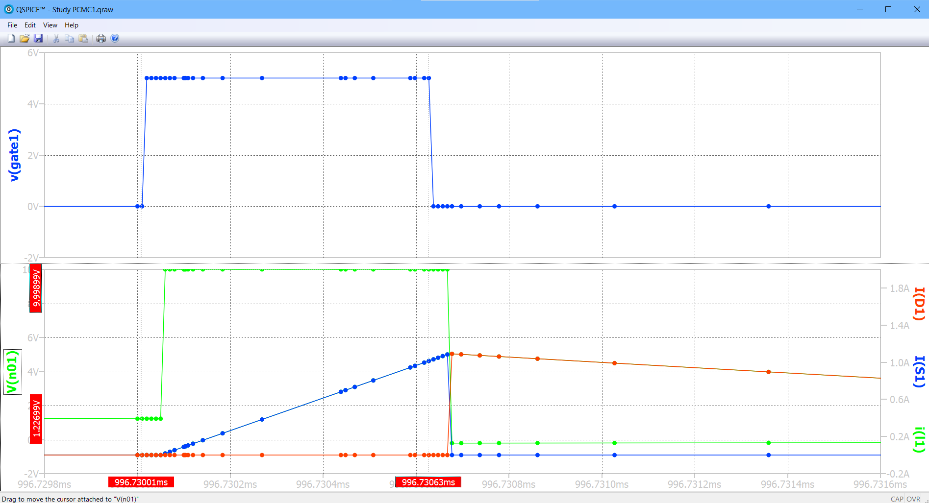
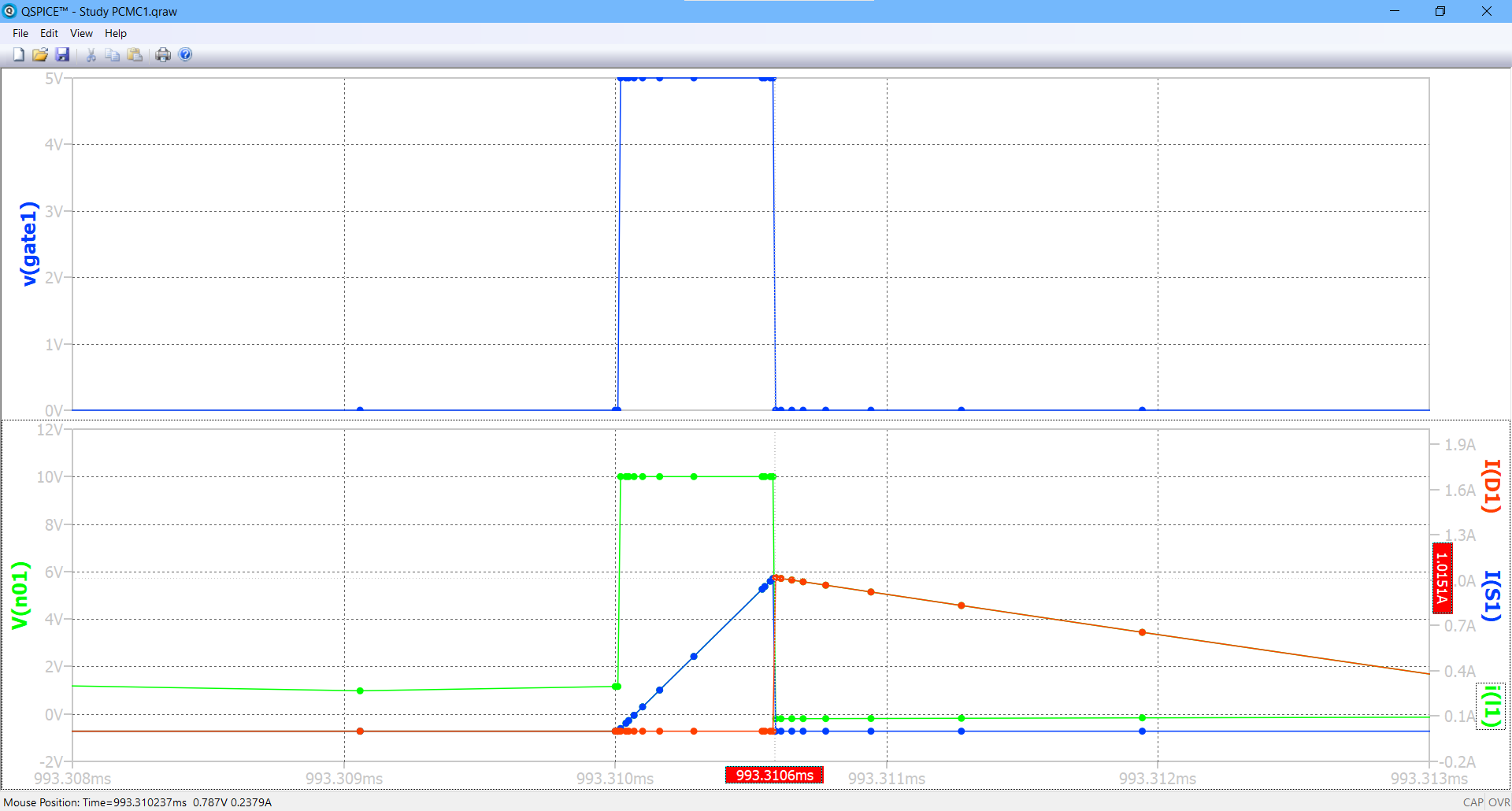
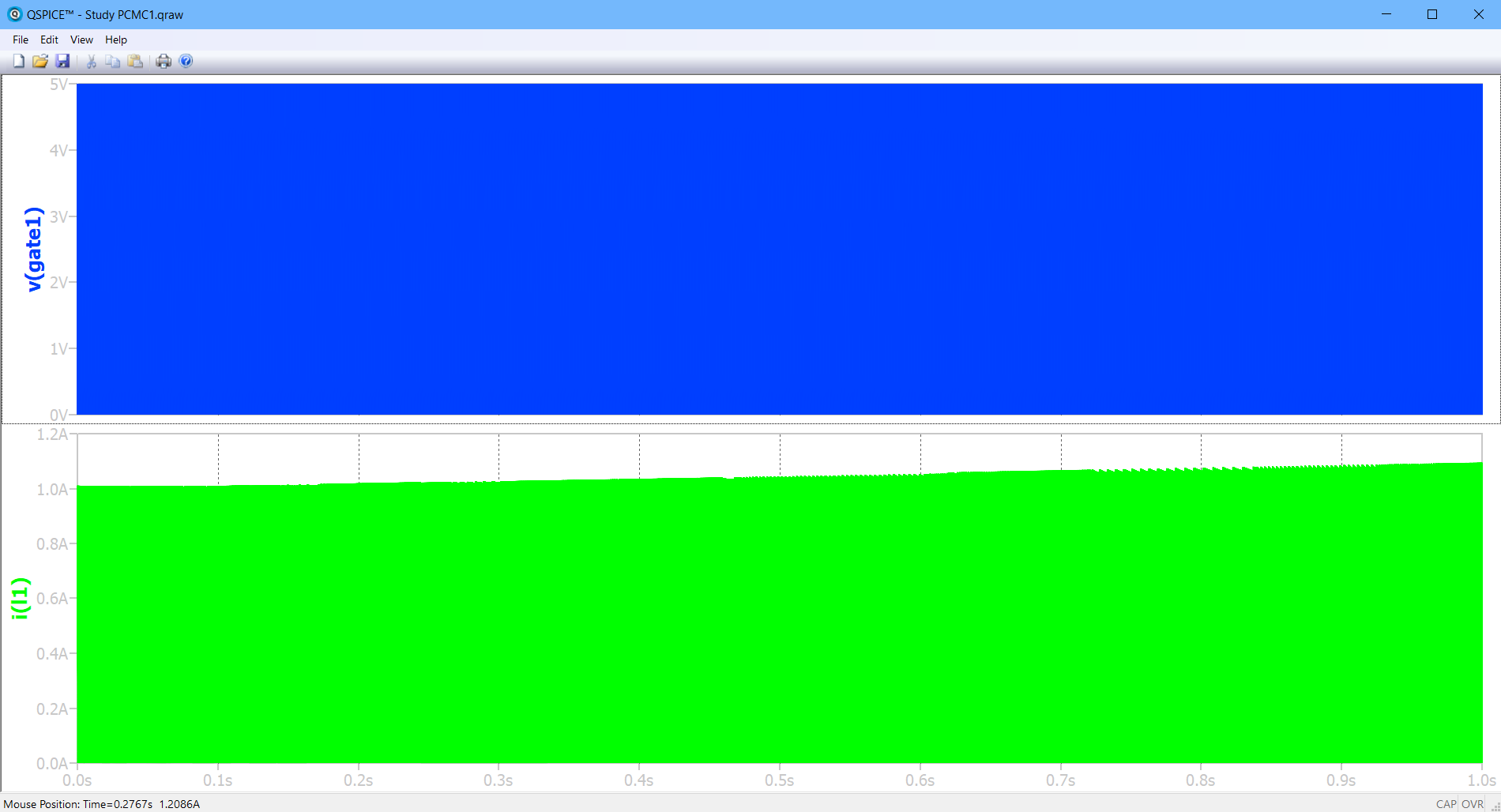
The question is, why doest the inductor current L1 current increasing higher towards the end of simulation ? (to be clear, there is no need for me to run the sim for 1s, except for curiousity)
From detail in the waveform, it appears if there is significant simulation step delays between when the gate signal rise and inductor current increase as well as between gate signal fall and inductor current decrease. Why is it happened?
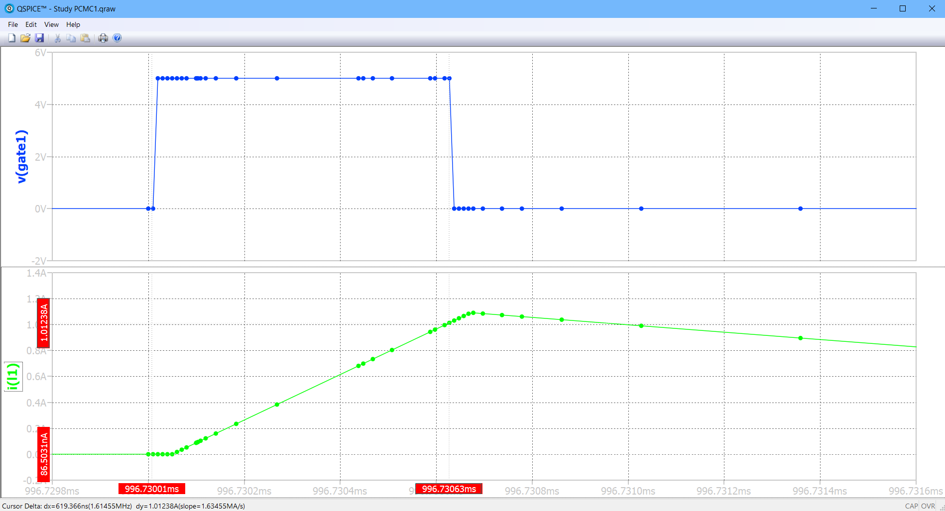
Looking for some clue…
Arief,