I’m looking to simulate a potentiometer with an audio (logarithmic) taper?
My goal is to see how a circuit reacts when I step a potentiometer position (0 to 100% => 1nohms to Max_val ohms).
Most potentiometers are linear. Hence, 25% pos = Max_val/4, 50% pos = Max_val/2, etc.
Audio taper pots are logarithmic so when inserted is certain audio circuits, it can provide the user with a linear effect. Such as volume, frequency gain and others to provide a linear effect to dB adjustments.
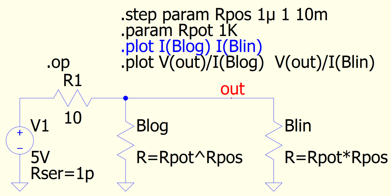
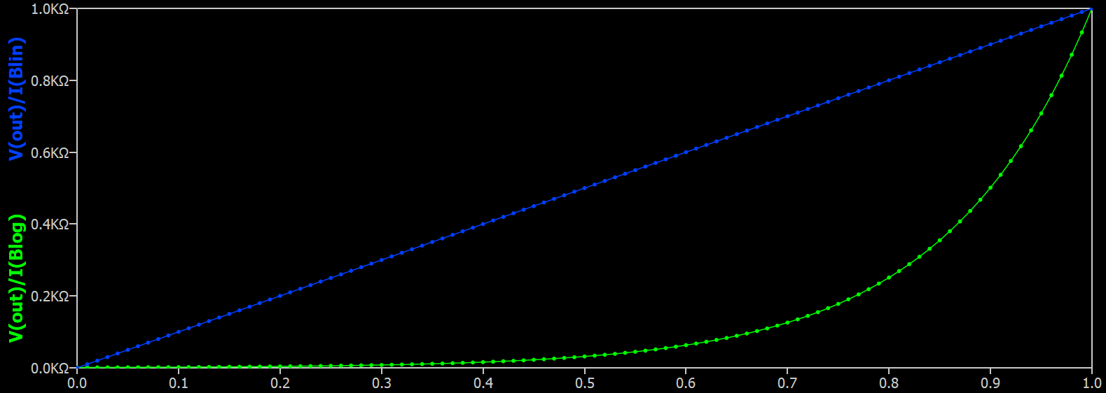
Any ideas? I tried using a B-source resistor with a log() function effect. I’m probably missing something.
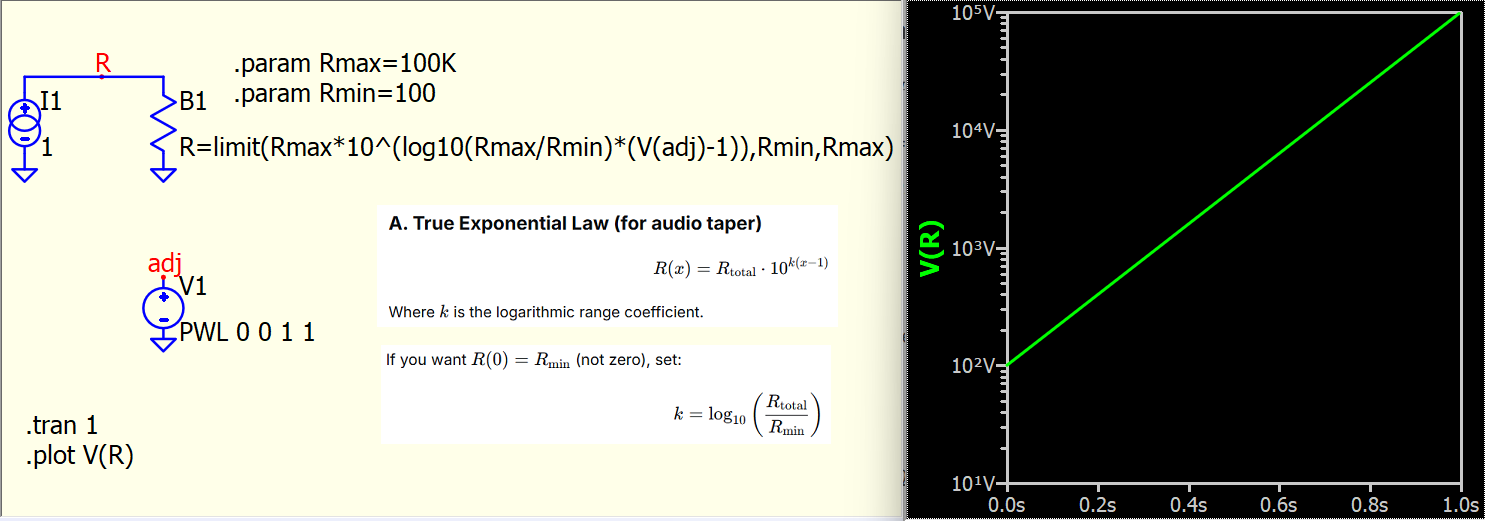
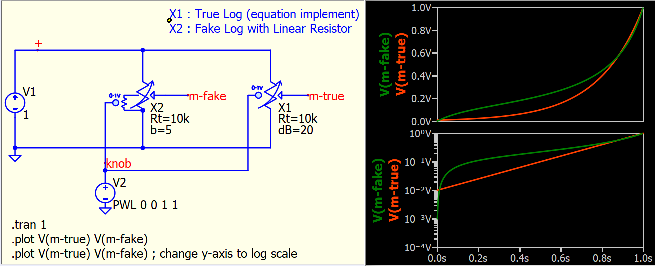
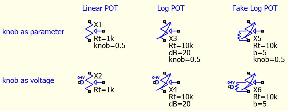
Studying logarithmic taper in potentiometers, I believe what you truly need is a potentiometer rather than a resistance change in a logarithmic scale.
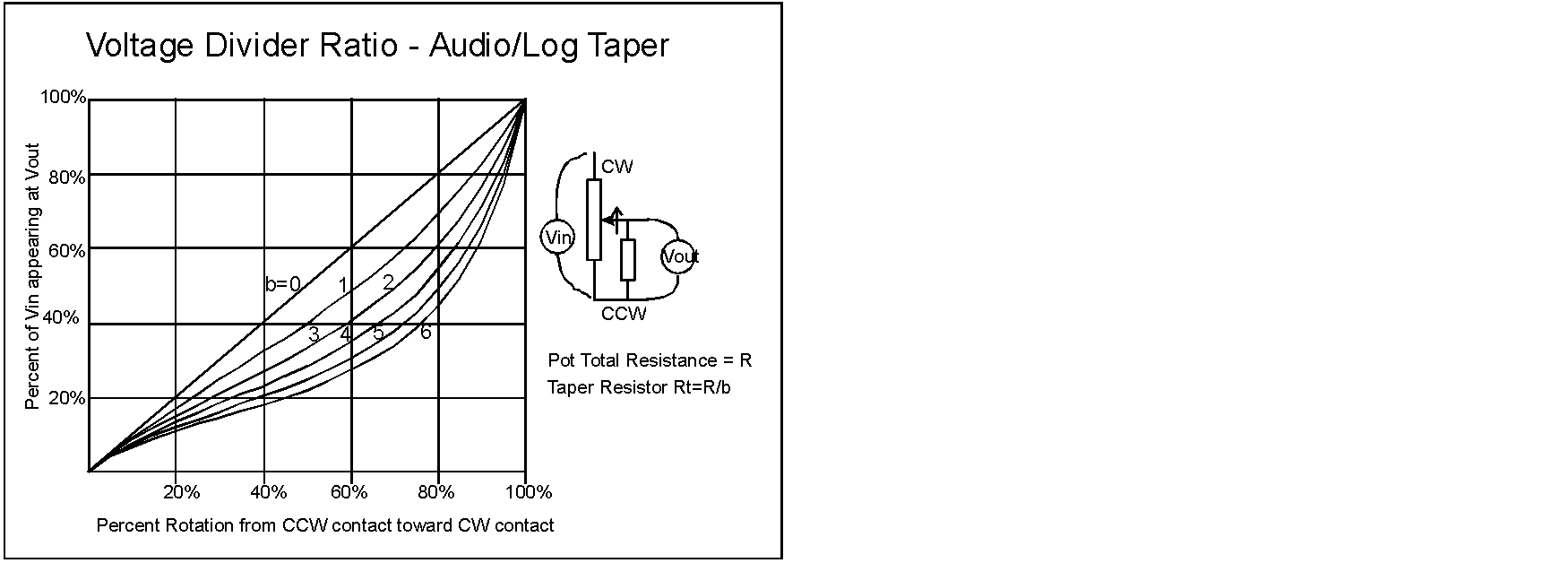
My search indicates that analog Log POTs are generally constructed with an additional resistor in parallel to a linear potentiometer to approximate a logarithmic output (pseudo log). Here is a reference for further information. The Secret Life of Pots
I’m still studying the information you’ve provided.
Just to let know why I’m inquiring about audio taper pots:
I’m working on a ‘simple’ project for a customer. It doesn’t involve audio but it does involve LED.
The customer wants a variable brightness LED that the user can control with a pot.
The first version was very simple. A simple linear pot with a max current limiting series resistance of 10 ohms to prevent LED burnout above rated current.
However, the customer didn’t like that the brightness had a ‘dead-zone’ in the pot (the voltage to the LED was below the forward voltage conductance) and then the rest of the pot travel had very dim to max brightness in a small degree of rotation. In addition the brightness in this small rotation was very non-linear.
He was looking for much smoother brightness control over the entire pot travel. I proposed that I can create a simple program on a CPU that can control the brightness very linearly by using the PWM function. He said “what’s the added cost?” When I told him, he said “Too costly”. I said there might be cheaper LED drivers. He said “Too costly”.
This is where the audio taper pot idea came into play. Audio taper pots are not cheap or easily found either. However, maybe I can satisfy him with the pseudo-log taper idea with a linear pot and a parallel resistor. Note: The 3-terminal configuration will not work in my situation since I need to pass up to 300mA to the LED.
More study and simulation is needed to satisfy the customer and my curiosity.