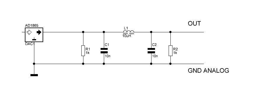
AD1865 - 18 bit DAC R2R
CURRENT OUTPUT + / - 1mA
Output Impedance: 1k7
How to simulate 1kHz sinus wave audio in +/-1mA current output from AD1865?
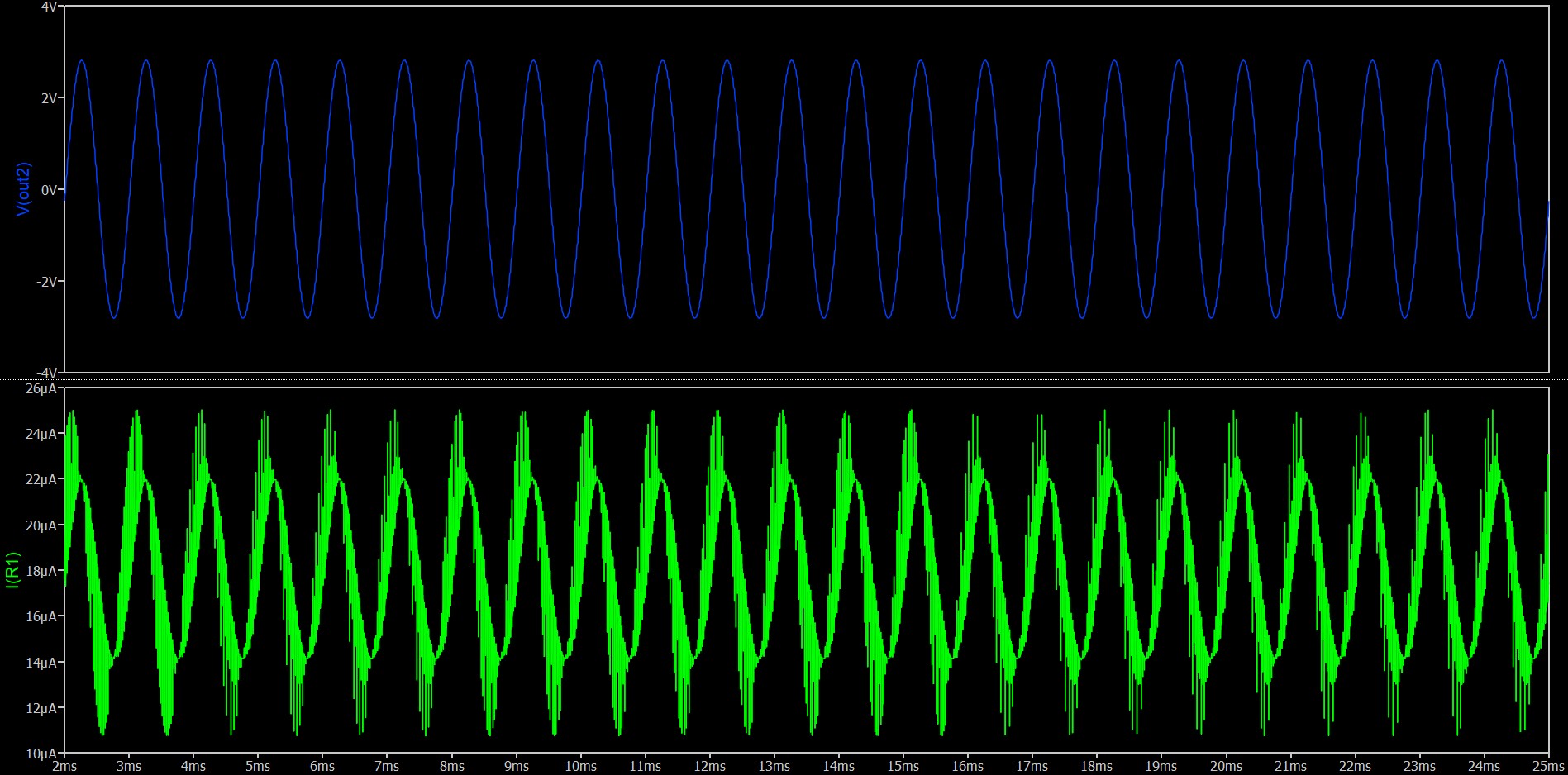
For example, if I use 500R resistor conversion in I-out, I receive c.a. 0.25Vpp sinus on it.
How to simulate real 1kHz sinus wave from 18bit DAC in current output?
How to simulate current output from many others DAC with sinus wave, when we have an information about current, and kind of current (f.e. TDA1541 works in other way than AD1865in current output - AD1865 current flowing out and in, or only flowing into the integrated DAC circuit in TDA1541)?
Is easy way to simulate that? Any idea?
Why? To simulate I/V conversion circuit.
I’m confused about what you are asking. You included an R2R ladder video example and then mentioned current outputs from an AD1865 (which outputs voltages, not currents).
Sooo, I’m trying to guess what you are trying to do…
I’m guessing that you are trying to simulate what would happen if you pass a sine wave into an ADC and then pass the digital ADC output into a DAC. You want (again, guessing) to have a QSpice schematic element that produces the output from the DAC (a stepped sine output) for analysis. You don’t need (yet again guessing) anything other than the schematic element that produces something like the stepped output from a DAC. You aren’t trying to specifically model the AD1865.
Hi!
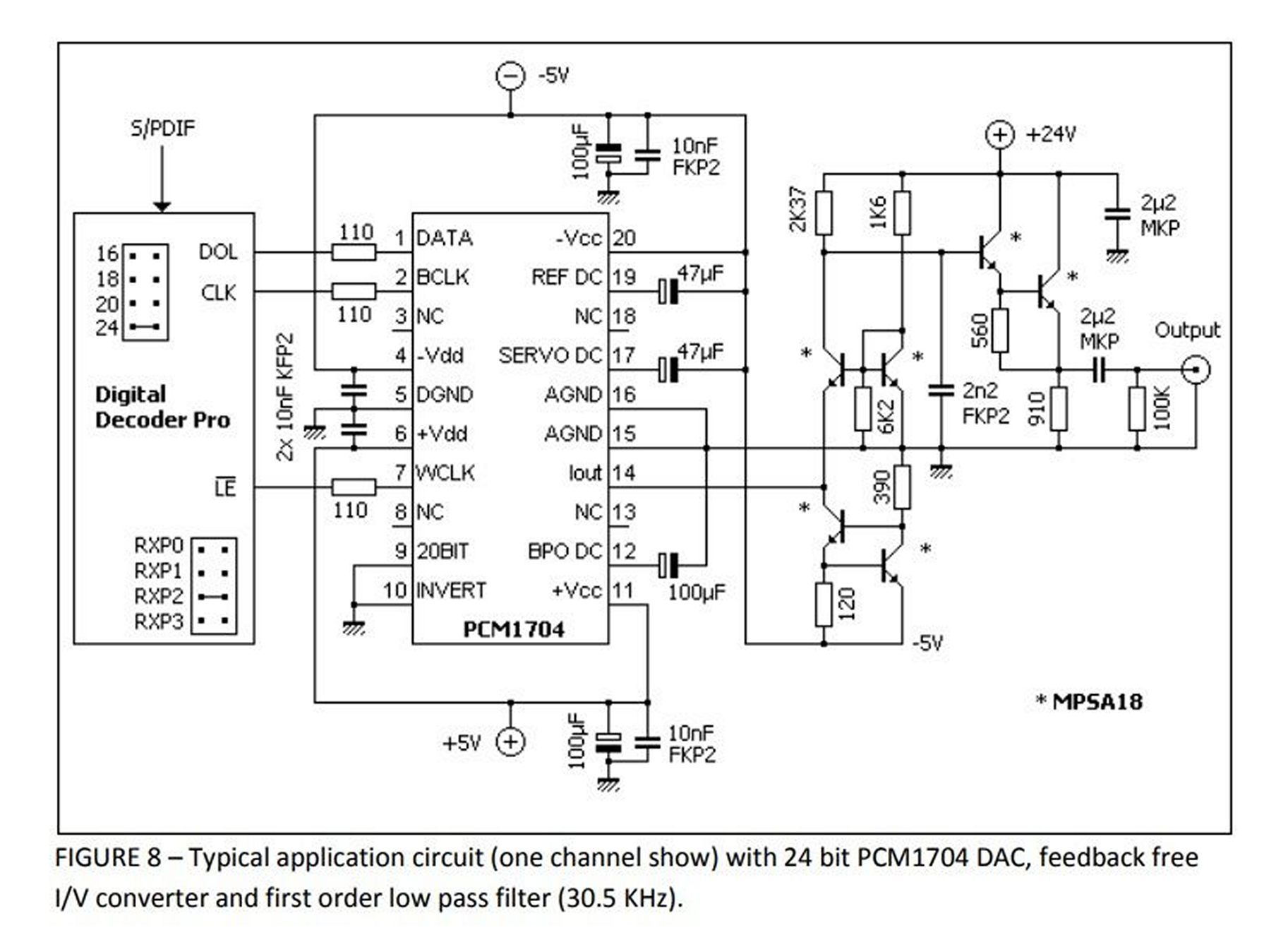
DACs generally have two outputs: current and voltage. We get high audio quality not by using the on-chip operational amplifier that offers a voltage output, but from the current output, where we have to do the current-to-voltage conversion ourselves.
The most common form of I/V conversion is converting current to voltage on a resistor.
This is not a perfect conversion, so more sophisticated circuits are built that can convert the current flowing in and out to an IC that has it so defined in its specification (e.g., +/- 1mA - AD1865), or there are circuits that work by modulating only the amount of current flowing into the circuit (TDA1541).
So, an I/V converter from the TDA1541 will not work properly with an I/V converter from the AD1865.
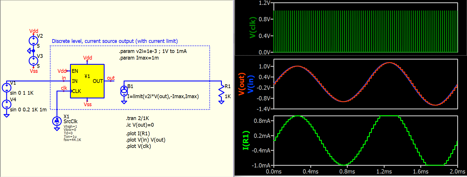
How to build a circuit model in QSPICE to study I/V converters giving a defined current value at the output, e.g. +/- 1mA?
The idea is not to modulate a sine voltage with a frequency of 1kHz, but to model a sine current variation of +/- 1mA with a frequency of 1kHz.
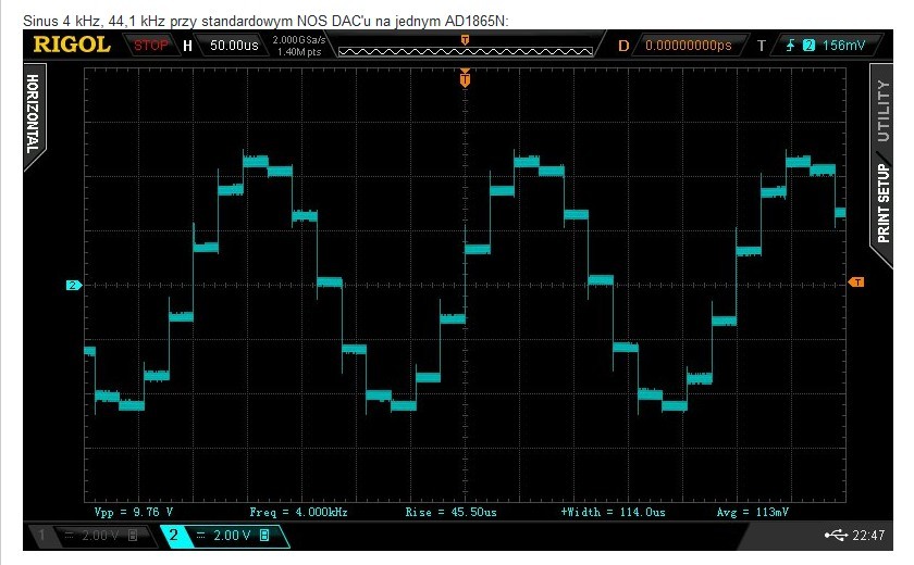
And the sinus output should not to be perfect, but like on screenshots from Rigol.
I need model of DAC to test, what happend with another I/V converters like Artwood or Eric Juenda circuit.