This is not a bug report !
I understand that the simulator is configured to improve the performance of it and I happy with it, but I would want to change the timestep of the simulator to have more points during a transition not too much of course; because there could be some issue in certain conditions, like one’s I have uploaded.
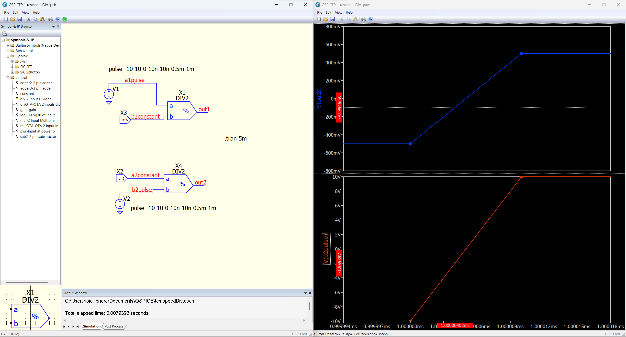
As we can see, I want to divide a constant which is 5V by a pulse and for example when the pulse is at -2V in the plot we see an output voltage of -97mV which isn’t -2.5V as it should be.
I found the option of the simulator in the help section, which one should I change to reduce the timestep?
By the way here is the subcircuit code of my divider bloc :
.subckt Div2 in1 in2 out
B1 out 0 V = V(in1)/V(in2)
.ends Div2
.tran IGNORED TSTOP [TSTART [MAXSTEP]] [UIC]
MAXSTEP is the maximum step size for simulation.
In you example, you can replace “.tran 5m” by “.tran 0 5m 0 1n”
where 1n is the maximum timestep in simulation
1 Like
Thanks it’s working but sadly this is a workaround, so I will leave my question open. Indeed, I would want a smarter behaviour of the simulator at critical moments like at a rise or at a fall. For example in another simulator without changing the maxstep, I have around 5 points at a transition so the time step is changing there. And for example I might have only 2 of them when the value isn’t changing.
Probably your “another simulator” cheat you with your maxstep setting and have own opinion how to simulate design. Did you shure that no approximation used for good waveform looking?
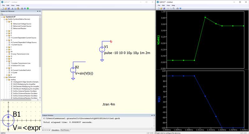
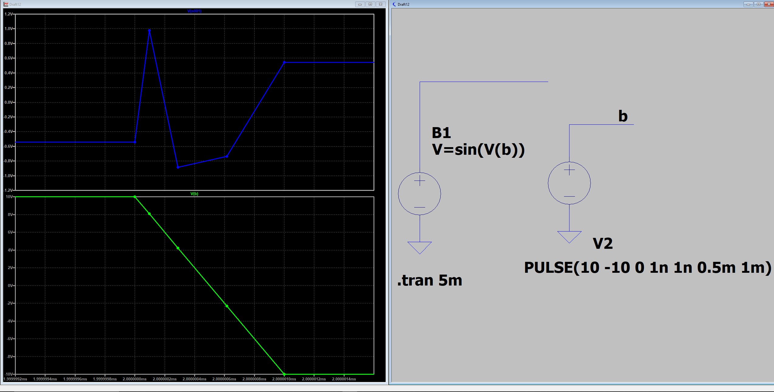
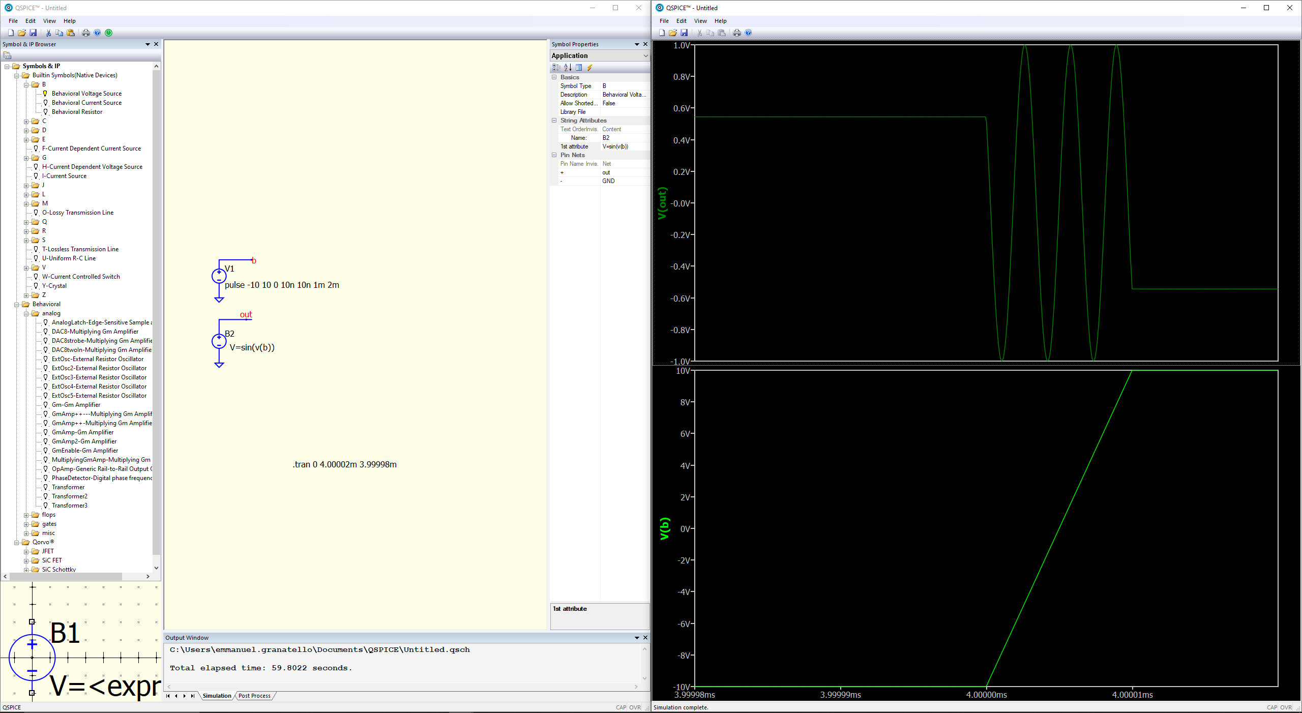
@LoicL.TPS it seems to me the division is actually not the problem. Look at what happens when dividing by a sine function:

It seems to me that the pulse, or better say its rise/fall time, are guiding the timestep “somehow”: this is just a hunch, don’t quote me please.
This is what happens with a longer rise/fall times. You can see that at least one more point appears if trise=50ns
It looks to me that in the pulse example the timestep is 30ns.
This is actually really a question for @Engelhardt : is there a default 30ns max timestep under the hood or there is another reason for this behavior?
To clear any doubt, the division by sine example above can solve with a 5ns circa timestep with 1Meg frequency because of the higher derivative (aka slew rate for linearly evolving voltages)… that’s also what would pull me towards the pulsed V source…again, I might be terribly wrong.
I am quite sure there is no approximation used for a good looking waveform. Actually, when there are more points the waveform is uglier because the simulator starts dividing by numbers close to 0.
Ergana
Think about result of division number by zero…
P.S.
To Forum Administation…
Is it possible to assign unuque numbers or ID`s for messages?
Sure it asympthotically tends to infinite…
But I don’t think Loic wants to see the number “infinite” appearing on the waveform viewer.
I guess his point is that if he ramps a voltage with a pulse V source, he expects to see some result datapoints during the ramp time, regardless of how fast the ramp is.
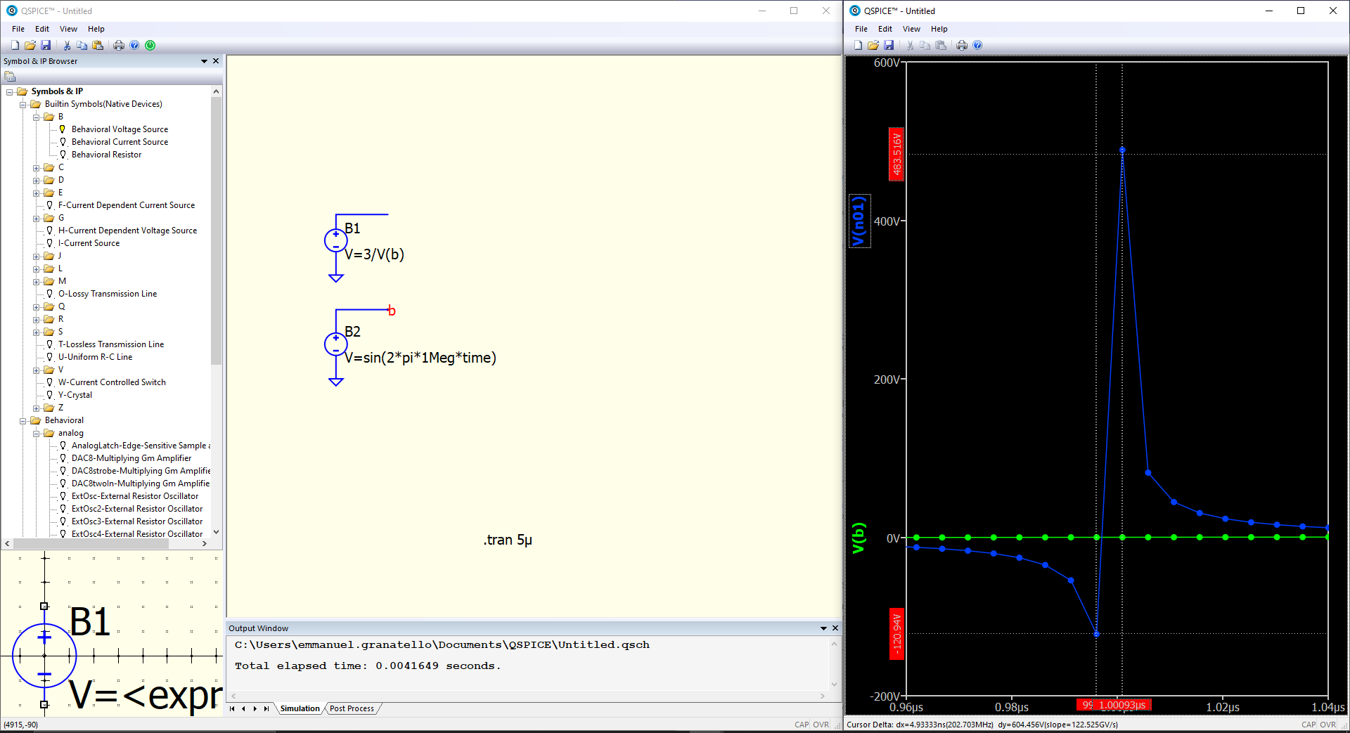
et voila’: no division, just a sine (intrinsically limited) but still no points between +10 and -10.

Hi Rhino, KSKelvin proposed this workaround some reply before.
LoicL does not seem satisfied with it, and I agree.
The simulator should find out by itself that there is some information loss without the user needing to force the maxstep in the .tran simulation.
I tried this with LTspice:
As you can see, the .tran command is as simple as it could be.
I am sure there is a way to obtain the same results also in Qspice.
I also would like to know how…
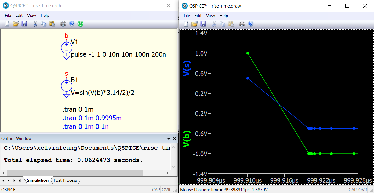
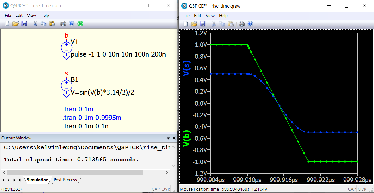
tested 3 .tran setting and their results.
case 1 is .tran 0 1m (= .tran 1m), in waveform viewer, no datapoints in fall time is shown
case 2 is .tran 0 1m 0.9995m, no MaxTimeStep is defined. This format is similar to case 1, but defined to start recording waveform data from 0.9995ms. in waveform viewer, ~20 datapoints in fall time
case 3 is .tran 0 1m 0 1n, forced MaxTimeStep to 1ns and similar to case 1 by collecting data from 0s. in waveform viewer, datapoints in fall time can also be observed
Not quite sure if data just discard for recording purpose in case 1 or adaptive time step algorithms in Qspice skip those.
If I think I must restrict the timestep of simulation, I add MaxTimeStep in .tran. Most important is to know what parameters can help in achieving the result we need. Have this practice long time ago since Pspice which was 20 years ago.

@KSKelvin thanks a lot for your investigation and insights!
The “issue” I have with imposing a MaxTimeStep is that it will impose the simulator to make calculations even at times when this calculation is not needed (i.e. when there is no, or incredibly little, variation of the results). I agree though that in other specific cases a MaxTimeStep is necessary.
Also, I would like to understand why in the LTspice case above there are more calculated datapoints points, very similarly to your case 2, while in your case 1 there are just 2 results during the ramp down.
You mentioned that case 2 starts saving values only from 0.9995m. That’s why I think your doubt is very legit:
[quote=“KSKelvin, post:20, topic:14734”]
Not quite sure if data just discard for recording purpose in case 1 or adaptive time step algorithms in Qspice skip those.
[/quote]."
I have the same exact doubt, I am sure @Engelhardt can help us with that.
@KSKelvin , following your cases I tried a couple of things:
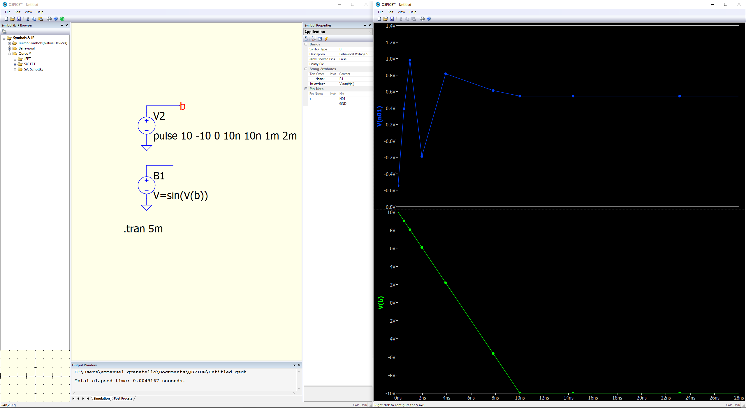
case 1 : reduced recorded simulation time to +/- 200ns around the falling ramp. I get more points, you can clearly see 3.5 periods (circa) of the a sine function. That’s what I expected. Simulation time is much larger than in my previous experiments.
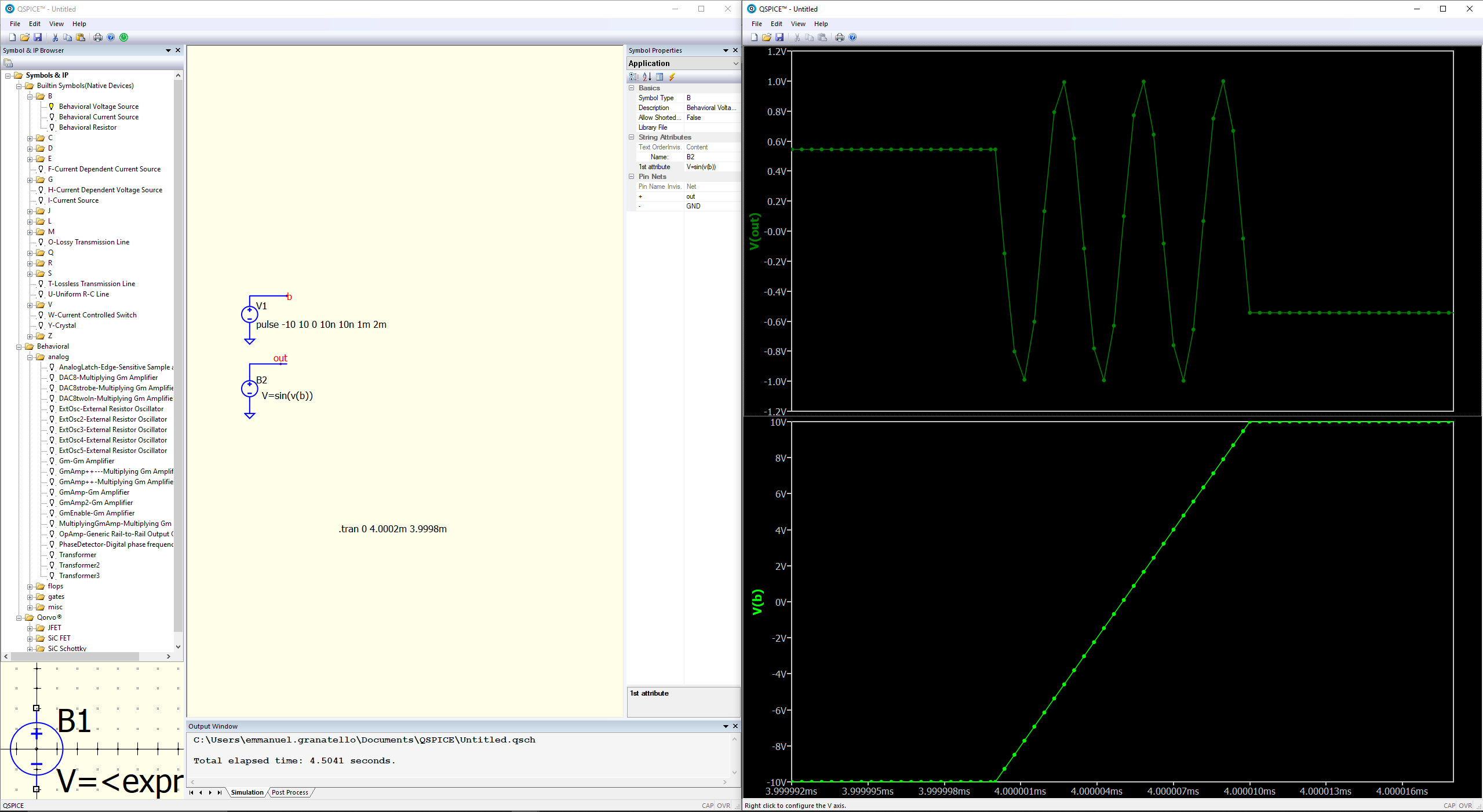
case 2 : reduced further recorded simulation time to +/- 20ns around the falling ramp. I get even more points, the sine function is very high.
So I wonder:
- why the time resolution changes with the recorded simulation time?
- is this a “by design” behavior of Qspice?
@LoicL.TPS , just a suggestion… I think it’s better you change the title of this topic to:
“B sources with pulsed sources as input: timestep changes with .tran recorded waveform time”
very interesting: I did not notice that during the first transition (0<t<10ns) some more points are computed.
Not a breakthrough but could spark some ideas…
This is a good suggestion, because thanks to @KSKelvin and you, the ‘issue’ is specified. But I haven’t found a way to change the topic name.
I am not sure if this is revelate. I do recall the TRTOL changes the timestep to small then there is a change to the voltage and increases the timestep when there is not change in the voltage. In spice, the default for trtol = 7. I ussually decrease tyrtol to 1 when I need more resolution without greatly increasing simulation. I hope this make sense. If I misinterpret the function of TRTOL, I am all ears.
Robert