building a TDOA system just try double receive buffer, but still just receive only one message from the closest device, other messages sent in the same time are all lost
simultaneously sending message may cause channel collision, which can result in only receiving either 1 or 0 message or even wrong message. You may use Time-slot based scheduler to send message at different slots or random delayed sending scheduler with CCA detection.
thanks @chxt set delay in tx can work, I will try your way
Personally I think the best solution I’ve seen to this issue was on the Dart system which could do TDoA between 2000+ tags at 1Hz and each tag would run for 5 years off a watch battery.
Their tags were transmit only devices with no attempt at collision avoidance or detection. Instead the repeat interval between updates was set using a deliberately low tolerance RC network so that the 1 Hz nominal update rate had a large plus or minus on it. Combine that with short packets and if there is a collision between tags for one update then there won’t be for the next update. You don’t need much of a rate difference for the relative timings to move by the length of a UWB packet over a second.
OK so you end up getting the odd collision and missing update but the system architecture is so much simpler, lower power and lower cost. And you can run far more tags that way than you could ever manage if you had a coordinated timeslot based system.
@AndyA thanks for you answer, instead of tag blinking, I make the anchor blinking and cal the TDOA in tag, and the anchor is connected by wire with sync signal
That works. It will all come down to how well you can sync the transmits from anchors and then track the clock difference between the tag and the anchors.
The timing resolution of the scheduled transmit command in the DW1000 isn’t great. But you will know what the transmit time will be in advance so you can include in the message the difference between the actual transmit time and the ideal transmit time.
Implementing a system like this but with wireless sync between the anchors has been on my to do list for a while, I’ve just not had a chance to try it yet.
I think what you said is actually ALOHA based system, but with smart power optimization using low tolerance RC’s timing characteristics. If used for asset tracking, this scheme seems better than cooperatively scheduler considering implementation cost/simplicity.
When used for self-positioning/navigation system, cooperative scheduler can guarantee constant update rate and is crucial for some robotic applications.
You mean there isn’t one solution that is optimal for all possible scenarios?
What a strange idea. ![]()
I think for these different cases: 1). asset tracking, 2). self navigation, currently different TDOA schemes(client vs server, or passive vs active) are working well in each case.
I’m thinking if there is some methods to combine these two schemes into a unified protocol supporting those scenarios, but didn’t find one currently.
It does depend on the application.
Asset tracking - Generally things are moving slowly or not at all so yield is not normally critical, as long as >50% of updates work then that will normally be acceptable. Position latency is also not critical. And the part that needs to know the location is the infrastructure not the asset. Generally you want to track lots of items with a low cost per item.
This implies a simple, low power tag with the complexity in the building structure. Absolute accuracy is normally less critical too, e.g. you need to know a shelf but not necessarily exactly where on the shelf.
Self navigation - Yield is more important, latency also matters more. Locations are needed at the tag. But you generally have low numbers of tags and so tag cost and complexity is less critical. Accuracy is also more important, you don’t want to drive into the wall.
Our system is aimed at an extreme example of the self navigation scenario. One or two items but needing 100 Hz updates with low latencies and errors of < 5 cm. We’re navigating / tracking at high speeds and with high accelerations.
The other complication is that the time to set the system up in a new location has to be minimal.
We ended up going the other route and using TWR. It significantly limits the number of tags you can track but eliminates the time synchronization requirement which lets us get the setup time down to around 30 minutes.
As mentioned above I want to look at a wireless sync TDOA system, it’ll remove the tag count limitations but I expect it to cost us some position accuracy.
hi, @AndyA,
could I ask you these questions:
-
We ended up going the other route and using TWR
what problem you encountered with wireless TDOA that makes you decide move to TWR system?
we are developing a (client-based, or passive-listening) TDOA system, currently we can only achieve ~5Hz update rate. (this rate may be improved if we complement protocol) -
I expect it to cost us some position accuracy
why do you think this may reduce positioning accuracy? personally I think I may achieve accuracy close to (or a bit less than) Decawave’s server-based TDOA system (aka, TTK1000). (we didn’t do this accuracy test as we haven’t finish our prototype till now)
-
Why TWR rather than TDOA?
We wanted minimal infrastructure in order to make setup simple, this means that the anchors require power and no other connections. TDOA requires time synchronization between the anchors which means we would need to implement a wireless time sync protocol.
We didn’t hit any issues with this time sync, we just never attempted it. I was the entire development team working on this project doing all of the hardware, firmware and software. TWR eliminated the need for the time sync and the initial requirement was for only one tag at a time. I decided to avoid adding an extra complication if I could.
Using TWR I could get 1 kHz range measurements (that later dropped to 800 Hz when I went to an 850kb/s data rate to improve range) which gave me more than enough data for positioning at 100 Hz. It’s not ideal since when moving at high speeds your ranges aren’t measured synchronously but the time between measurements to the same anchor is small enough that interpolation over the time intervals is sufficient to compensate for that.
I have plans to improve this, by playing some games with the radio protocol I think I can get around 2.4 kHz range measurements with all anchors effectively measured simultaneously while still using a TWR based system. -
Why do I expect TDOA with wireless sync to be less accurate?
Currently we use TWR which is effectively averaging 4 measurements. Assuming measurement error is random noise (it’s not completely but is close enough that this isn’t completely invalid) then averaging 4 measurements reduces noise by a factor of 4.
TDOA we would be using a single measurement per anchor meaning more noise in the measurements. Plus any synchronization errors will be added to that, potentially doubling the error although hopefully good filtering would eliminate most of that.
I should point out that this isn’t based on any actual experimental results, it’s purely my gut feel for what I would expect to see and so could be completely wrong.
thanks for your detailed explanation, I’ll do some test for evaluating some days later.
This isn’t correct. No pure aloha system (like the Zebra DART) can have the system capacity that a fully slotted system can have.
To illustrate, here are the system capacities for pure aloha and slotted aloha:
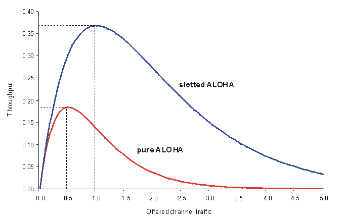
In pure aloha, which is what the DART system is, the tag transmits with jittered time intervals. The maximum non collided system capacity occurs when the offered traffic is 50% of channel capacity and in that case, 18% utilization occurs (36% of the packets get through cleanly). If your offered traffic goes higher, then you actually get less throughput due to the rapidly increasing probability the packets collide. Since tags only transmit, they never know when they are on the backside of the curve if the tag density increases so the system fails to perform and there’s no way to manage that other than reduce the number of tags in the area.
An improvement on pure aloha is slotted aloha where packets can only be offered at defined internals. This requires tags which can synchronize to a clock so is rarely done since it is a small step to a fully slotted system once you have that.
A fully slotted system has tags that periodically receive network synchronization messages and are assigned a specific slot that assures no collisions. Thus you can achieve 100% system utilization and suffer no packet losses.
We’ve built systems that have been pure aloha, slotted aloha, and fully slotted. They each have a place of utility, but the capacity winner is always the fully slotted.
There is a further practical factor that makes aloha systems worse. The user may have a requirement that they hear from a tag every so often. Let’s say that is within 3 seconds. If you set the aloha interval to 3 seconds, then a collision means you miss that packet. So, to compensate, you set the interval to 1 second and hope you don’t miss 3 packets in a row. In essence, the unpredictability of aloha leads users to set the interval faster leading to more collisions. This doesn’t happen in a slotted network since the system is predictable.
Our TDoA system operates at 3400 locates per second and we expect to increase that to over 6000 soon. So we are already doing better than the DART claimed rate of 2000 LPS. Having worked with those who have used the DART system, the quality of output at 2000 LPS is fairly poor as well, often requiring post filters to sort out the mess. You don’t have that in fully slotted.
As to battery life, an aloha system is not significantly less battery usage than a properly designed slotted system. The key to this is what we call “low power precision sleep”. It takes about as much power to run an RC timer as a 32 KHz crystal timer, so if you can model the crystal accurately enough, you can sleep long periods of time and wake up with microsecond precision and hit your slot. In our experiments, we can listen for a network time sync about every 2 minutes and maintain microsecond time slot lock. While that receive does take some power, it is on for only about 120 us in 2 minutes, that’s a duty cycle of 0.0001% which makes average receive power less than half a microwatt.
The ability to send the tag a message also saves power. You can control the tag beacon rate to lower it if the tag isn’t moving much, or if the tag is away from the network, it can go silent and wait to be back on network. If the tag density increases in an area, tags can be told to slow down. With a slotted tag, the user is assured of a regular interval so sending “extra” beacons is reduced. All of these factors make slotted tags LESS overall power in practical applications.
A further complexity is that the DART system tags transmit all the time which makes shipping them a problem. A slotted tag will cease after a certain time off network and restart when it hears a network again.
If maximum system capacity is your goal, aloha is not appropriate, you need fully slotted.
Mike Ciholas, President, Ciholas, Inc
3700 Bell Road, Newburgh, IN 47630 USA
mikec@ciholas.com
+1 812 962 9408
It comes down to a trade off between complexity and performance.
A DART tag creates a UWB transmitter using an 8 pin PIC, an xor gate, a transistor and some cunning board layout. In terms of simplicity it was a brilliant piece of design by multispectral.
Is it the theoretically best possible solution? No.
Was it a wonderfully simple and cost effective piece of engineering that gave them vastly better performance than their contemporary competitors? Yes.
At the time any timeslotted competitors had trouble with more than 100 or so tags.
That system design hasn’t been touched for probably almost 15 years now, I’d hope that any modern system still being actively developed was significantly better than it.
The DART tag lacks sophisticated modulation, it basically is an impulse UWB which is received as a time domain pulse using an energy detector. This makes those pulses very susceptible to noise as any RF impulse looks like the pulses which requires a signal processing to separate out. It does make for an inexpensive tag, but expensive receivers, and probabilistic receive reliability. With tags lacking receive capability, the system is relegated to crude operation, basically all it can do it randomly beacon without any remote configuration or control, nor sync up with infrastructure to optimize performance or slotting.
The DW1000 is very different in that it creates a specifically modulated signal that can be more selectively received and decoded. This is why a DW1000 can work in situations a DART tag won’t, and a DW1000 can carry far more information in a packet than the DART. With a DW1000 having a receiver, that opens up all sorts of capabilities to send control information and to sync to infrastructure to enable slotted aloha or fully slotted systems with the resulting high performance and lack of randomness.
The two systems are really night and day as to the fundamentals of the radio signal.
Regardless of the modulation method, a slotted system provides the highest possible system capacity. You simply can’t do better than 100% utilization, and slotting is the only way to get that.
Mike Ciholas, President, Ciholas, Inc
3700 Bell Road, Newburgh, IN 47630 USA
mikec@ciholas.com
+1 812 962 9408
@chxt @AndyA do you know how to get the blink frame receive timestamp correctly?
using
uint32_t timestamp = dwt_readrxtimestamphi32();
to receive a 1Hz blink msg
first msg -> 968943007, second msg -> 1218544485
In [124]: (1218544485 - 968943007) * DWT_TIME_UNITS
Out[124]: 0.003906273130759215
0.003906273130759215 is far away from 1 s
DWT_TIME_UNITS is the number of seconds per tick and is around 15ps. Which means a 32 bit counter will wrap around every 0.06 seconds.
To measure times over a few milliseconds you need to use the full 40 bits of the timestamps.
static uint64_t get_rx_timestamp_u64(void)
{
    uint8_t ts_tab[5];
    uint64_t ts = 0;
    int i;
    dwt_readrxtimestamp(ts_tab);
    for (i = 4; i >= 0; i--)
    {
        ts <<= 8;
        ts |= ts_tab[i];
    }
    return ts;
}

uint64_t timestamp = get_rx_timestamp_u64();
Thanks for your reply! @AndyA I have also try get_rx_timestamp_u64 function from example code, but I get more confused, it’s negative and also not correct
first msg -> 3371524944, second msg -> 2845051570
In [127]: (2845051570 - 3371524944) * DWT_TIME_UNITS
Out[127]: -0.008239329395783253
@AndyA I trying to play around with the timestamp by blew code
    uint64_t last_dw_systime;
    while (1)
    {
      uint64_t timestamp = get_system_timestamp_u64();
      char dataseq[50];
      sprintf((char*)&dataseq, "current: %lu \r\n", timestamp);
      port_tx_msg(dataseq, strlen(dataseq));
      sprintf((char*)&dataseq, "diff: %lu \r\n", timestamp - last_dw_systime);
      port_tx_msg(dataseq, strlen(dataseq));
      last_dw_systime = timestamp;
      HAL_Delay(60);
    };
when delay time below 60ms the diff seems to be correct, but when delay is higher than 60ms, the diff is much smaller, so I guess it need to add a schedule to tick, so how cloud I know how many tick schedule has been overflow