I have been adding .MODEL component text from a very useful source of these files located at http://bordodynov.ltwiki.org/ to the appropriate component text file e.g. C:\Program Files\QSPICE\NPN.txt and all seems to work as they appear on the selection guide when adding e.g. an NPN BJT. How can I do something similar if the only component source is in the form of a SPICE SUBCIRCUIT? I can add such a subcircuit to a schematic using Mike E’s method but how can I make it a permanent option in QSPICE?
You can program a symbol to include a file. It’s the “Library File” attribute.
Also, if make a symbol with the automatic symbol generation feature, the subcircuit is included in the symbol.
–Mike
1 Like
If I make a symbol from a .SUBCKT file for a quad op-amp e.g. LM324, I assume I just make one instance of a single LM324 op-amp, save it as LM324.qsym and add it as many times as necessary to a simulation schematic? i.e. not paste the .SUBCKT into the symbol editor 4 times to make a quad op-amp symbol - when trying this I notes that all the port numbers disappear from 3 of the four op-amps added to the symbol. LM324 .SUBCKT follows:
*LM324 Low Power Quad OPERATIONAL AMPLIFIER MACRO-MODEL
*//////////////////////////////////////////////////////////
*
- connections: non-inverting input
-
| inverting input -
| | positive power supply -
| | | negative power supply -
| | | | output -
| | | | | -
| | | | |
.SUBCKT LM324/NS 1 2 99 50 28
*
*Features:
*Eliminates need for dual supplies
*Large DC voltage gain = 100dB
*High bandwidth = 1MHz
*Low input offset voltage = 2mV
*Wide supply range = ±1.5V to ±16V
*
*NOTE: Model is for single device only and simulated
-
supply current is 1/4 of total device current. -
Output crossover distortion with dual supplies -
is not modeled.
**INPUT STAGE
*
IOS 2 1 5N
*^Input offset current
R1 1 3 500K
R2 3 2 500K
I1 99 4 100U
R3 5 50 517
R4 6 50 517
Q1 5 2 4 QX
Q2 6 7 4 QX
*Fp2=1.2 MHz
C4 5 6 128.27P
*
COMMON MODE EFFECT
*
I2 99 50 75U
*^Quiescent supply current
EOS 7 1 POLY(1) 16 49 2E-3 1
*Input offset voltage.^
R8 99 49 60K
R9 49 50 60K
*
*OUTPUT VOLTAGE LIMITING
V2 99 8 1.63
D1 9 8 DX
D2 10 9 DX
V3 10 50 .635
*
SECOND STAGE
*
EH 99 98 99 49 1
G1 98 9 POLY(1) 5 6 0 9.8772E-4 0 .3459
*Fp1=7.86 Hz
R5 98 9 101.2433MEG
C3 98 9 200P
*
POLE STAGE
*
*Fp=2 MHz
G3 98 15 9 49 1E-6
R12 98 15 1MEG
C5 98 15 7.9577E-14
*
COMMON-MODE ZERO STAGE
*
*Fpcm=10 KHz
G4 98 16 3 49 5.6234E-8
L2 98 17 15.9M
R13 17 16 1K
*
OUTPUT STAGE
*
F6 50 99 POLY(1) V6 300U 1
E1 99 23 99 15 1
R16 24 23 17.5
D5 26 24 DX
V6 26 22 .63V
R17 23 25 17.5
D6 25 27 DX
V7 22 27 .63V
V5 22 21 0.27V
D4 21 15 DX
V4 20 22 0.27V
D3 15 20 DX
L3 22 28 500P
RL3 22 28 100K
*
*MODELS USED
*
.MODEL DX D(IS=1E-15)
.MODEL QX PNP(BF=1.111E3)
*
.ENDS
How do we make parameters in the subcircuit user supplied? Same as LTspice {}?
Your question is unclear. Does p.35-36 in this guide is what you are looking for?
You have an option to download this guide in Github page.
Qspice - General Reference Guide by KSKelvin.pdf
1 Like
Is there a way to add more than one component in a library and this may be accessed by that component created?
I can only post pictures as my membership status does not permit me to attach what I’d like to generate
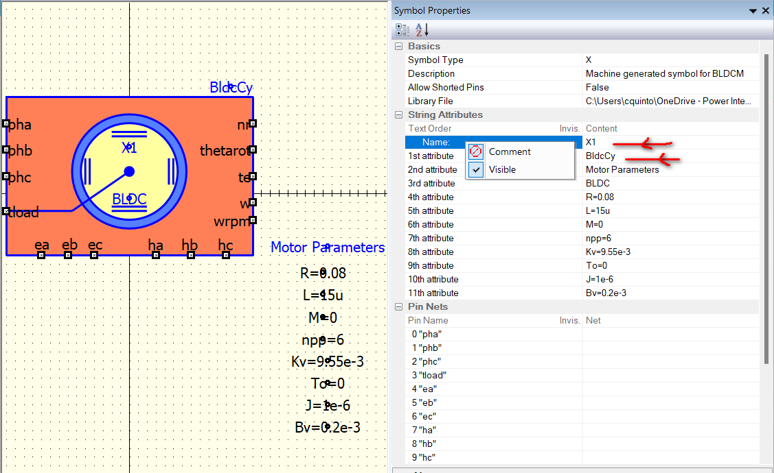
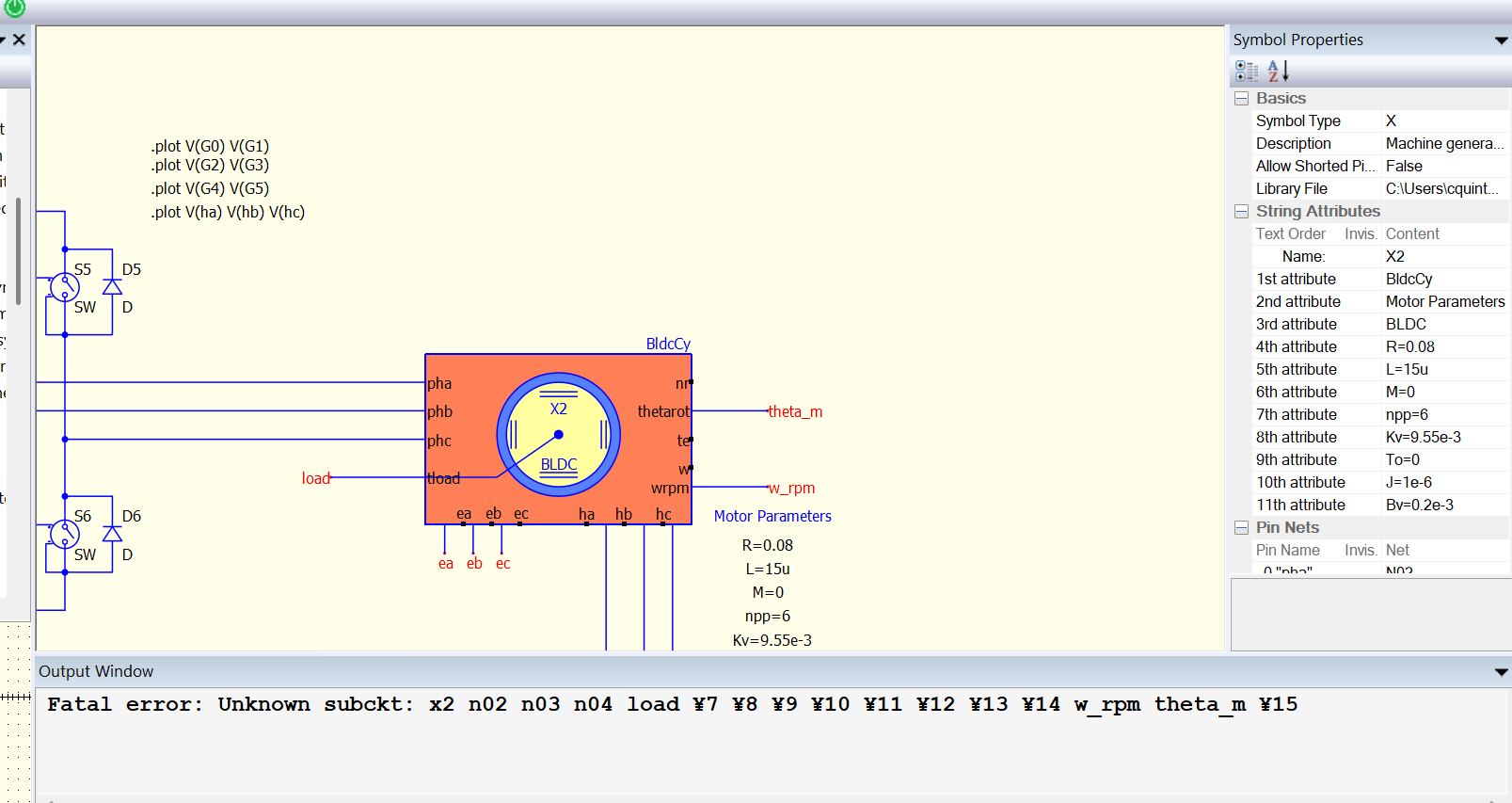
I wonder why and how to name this created component correctly as I already named it BldcCy but the subcircuit is still named as X2. When I change the script to X2, still the same error.