I am using analog transformer, it work, but it doesnt have center tap as I want to get the voltage from AC 0-65V from main AC 230V. How to get this done in QSPICE ?
1 Like
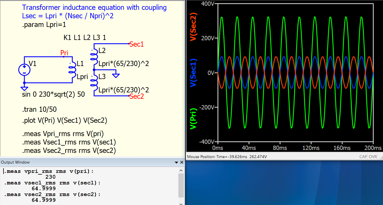
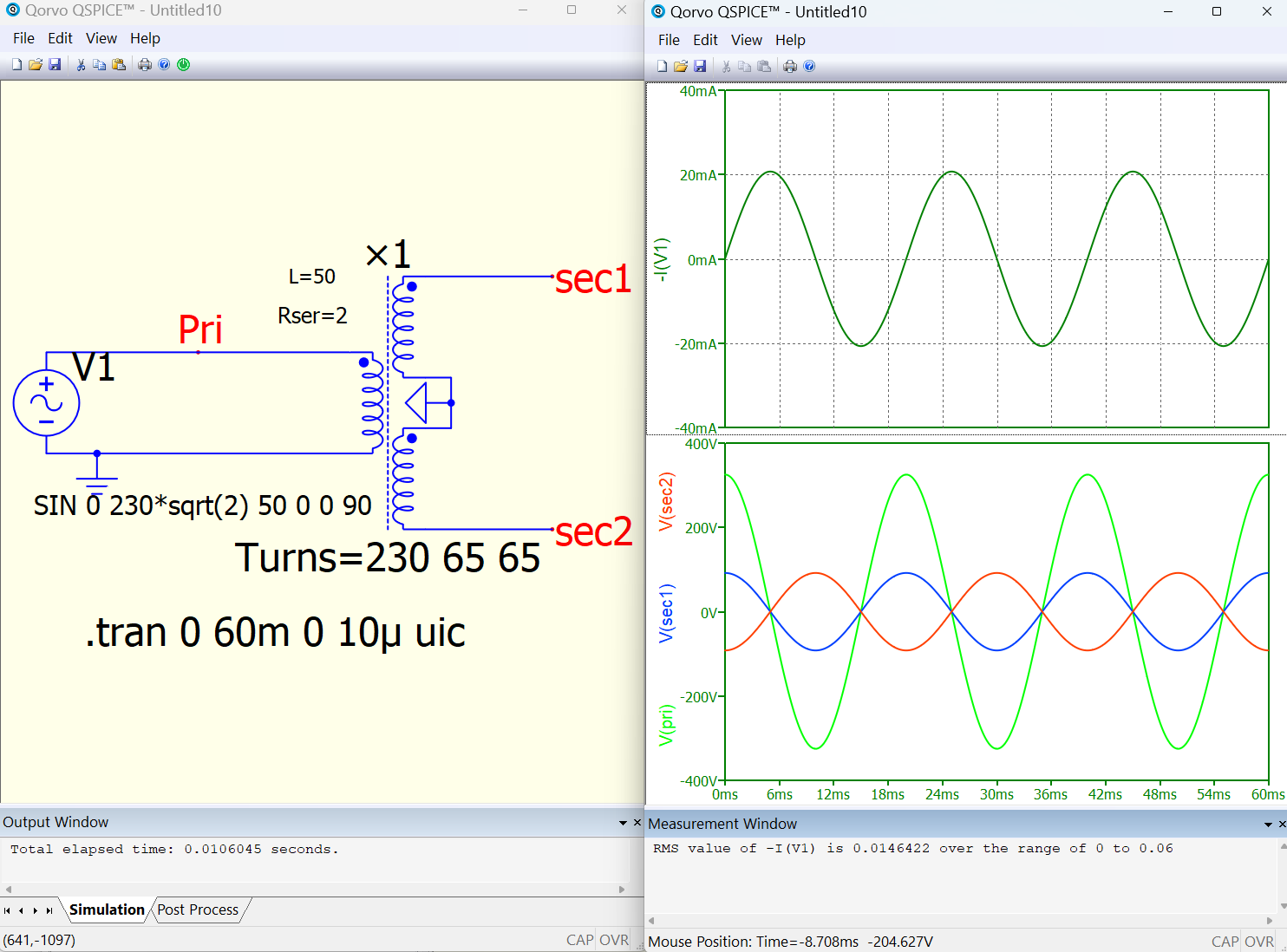
Center tap can also be understand as 1 input 2 output transformer. It can model by multiple coupled inductors or Qspice ×-device.
Standard Qspice ×-device symbol can be found in Symbol & IP Browser → Behavioral → analog → Transformer / Transformer2 / Transformer3
Transformer-MultipleOutput-Coupling.qsch (3.7 KB)
Transformer-MultipleOutput-×-device.qsch (5.2 KB)

1 Like
I got it. Thank you very much. The device Reference Guide file from your github cannot be open, seem like the file cannot be render.
Thank you very much. I have try yours solution too. I got it.
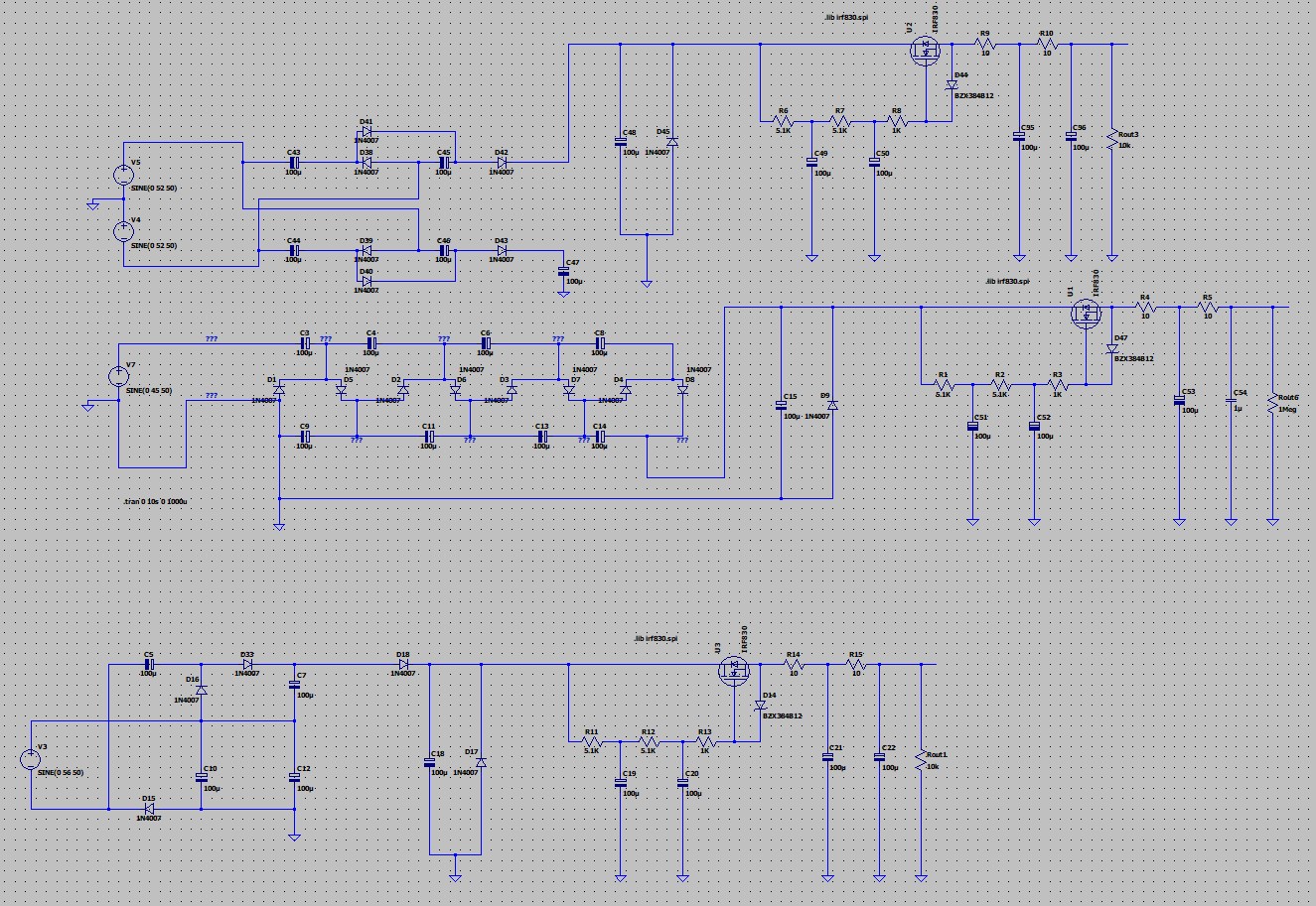
One question - I woluld like to test anode PSU for my headphone tube amplifire. I was testing some circuits in LTSpice, but I want to test this in Qspice with real transformer simulation.
For example, I want to test transformer 15V-0-15V 42VA - in voltage multiplier to 170V 200mA output.
How to tell Qspice, that simulated transformer is for example 1A current in output, to test voltage multiplier in anode PSU.
For example, if I would like to see if a voltage multiplier will allow a guaranteed current output of 200mA, is it possible to define such a current output for a transformer simulation?
Transformer current output - can we define it from transformer and how? THX.
It is possible to put the simulation file here
I edited that post and with simulation files upload in there.
1 Like
Hello @bordodynov,
Can you please share the schematic file?
Unfortunately, there are limited information transfer options on this forum. Here are my building blocks for building transformers:
Transformer200W.qsch (12.0 KB)
CoreJA_Gap.qsym (1.2 KB)
COREJA_GAP_H_B.qsym (1.6 KB)
220Vmy.qsch (21.1 KB)
test push pull - ABv3.qsch (18.2 KB)
test push pull - ABv2.qsch (17.0 KB)
Winding_CR.qsym (1.1 KB)
test push pull - ABv1.qsch (17.1 KB)
CORE_AL.qsym (463 Bytes)
Hist3.qsch (4.5 KB)
Hist2.qsch (6.8 KB)
transfor2.qsch (10.5 KB)
transfor1.qsch (6.5 KB)
Hist1.qsch (6.5 KB)
Tr_1_10_10.qsch (5.2 KB)
Winding_LCR.qsym (1.1 KB)

2 Likes
I’ll try to transfer my libraries for now:
https://kazus.ru/forums/showthread.php?t=122365
https://disk.yandex.ru/d/71M79VuY5sOWew
1 Like
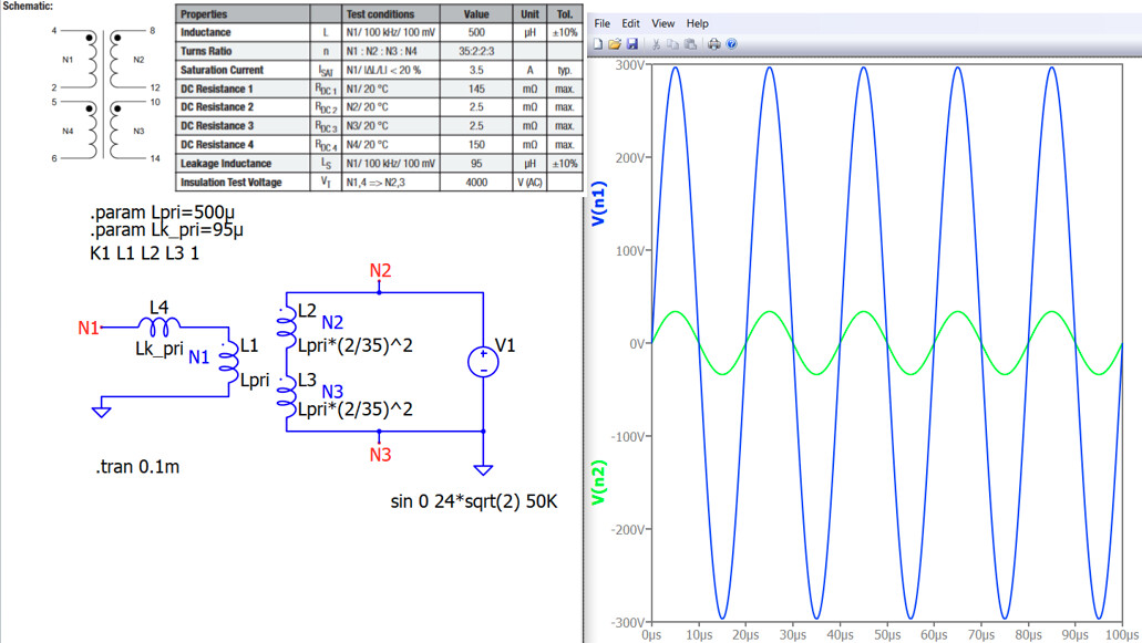
Hi guys, could you help me to check my transformer model and how to calculate the leakage inductance and the saturation current in secondary winding (N2 and N3). Actually I would like to invert the transformer to step up the voltage. I connected N2 and N3 as input and N1 for the output. Thank you.
Transformer_model.qsch (4.1 KB)
1 Like
This transformer with a primary inductance of 500µH and a leakage inductance of 95µH, where leakage ratio of 19%!! Was this transformer designed for a very special purpose? This leakage ratio doesn’t quite make sense.
Are you truly operating this at 50 kHz from its secondary? If you probe the current of V1, it is about 33 A peak as N2, N3 inductance is just ~ 1.6uH and XL1, XL2 @ 50kHz is only 0.5 ohms.
Not really, it was for test. I am looking for a transformer that ready on the market to step up voltage. I won’t to custom transformer design.
Well, you have already modeled the leakage inductance.
To model saturation with a non-linear inductor in QSpice, it requires an ideal transformer paired with a non-linear inductor (using instance parameters Isat, Satfrac, and Lsat), as the K-statement does not support non-linear inductors.
Your spec defines from primary to secondary, that why the verification is performed from primary to secondary. In your simulation, just put the source at secondary and load at primary.
Transformer_model-Saturation.qsch (5.7 KB)
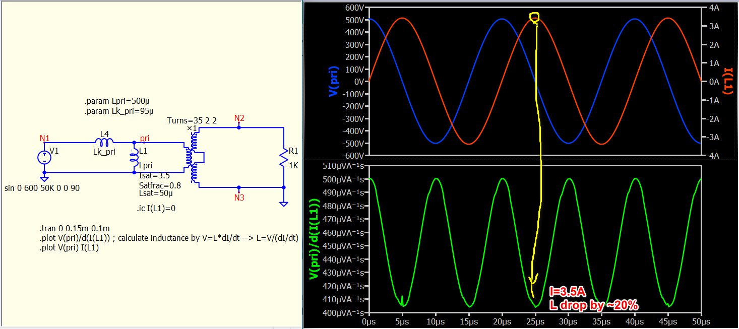
1 Like