How to get RMS value of voltage across a component in Qspice when AC supply is used, I checked the power across the resistor by enabling .options savepowers=1,
This one is Pavg I think, and i’m not getting a exact value like rms power
How do this in qspice
It is possible to calculate power in RMS, but are you referring to .tran analysis?
But why calculate RMS power in AC system? We calculate voltage and current in RMS, but power in RMS has no physical meaning.
RMS Power vs. Average Power | Analog Devices
Yes, I needed the RMS voltage for further calculation of power, and I has got it through the .meas methods.
Now I need to know that, is there any option to add a custom parameter which need to see (RMS Voltage/current) like I see the voltage or current with the cursor or can I edit the equations which calculates and show the voltage/current while using the cursor
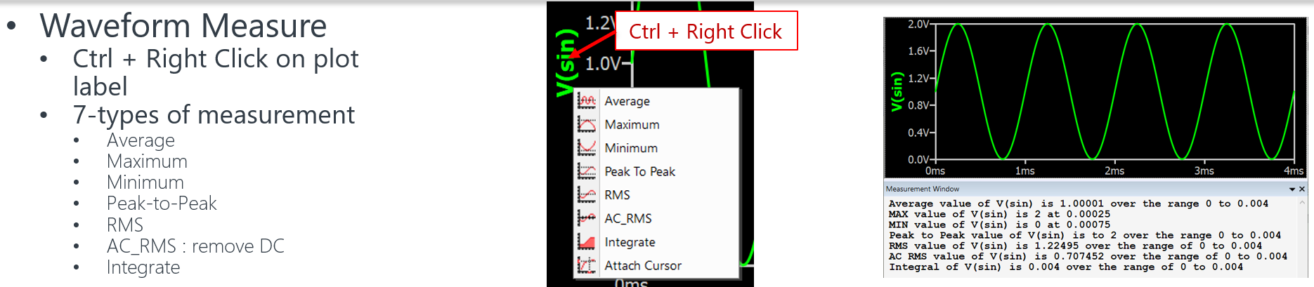
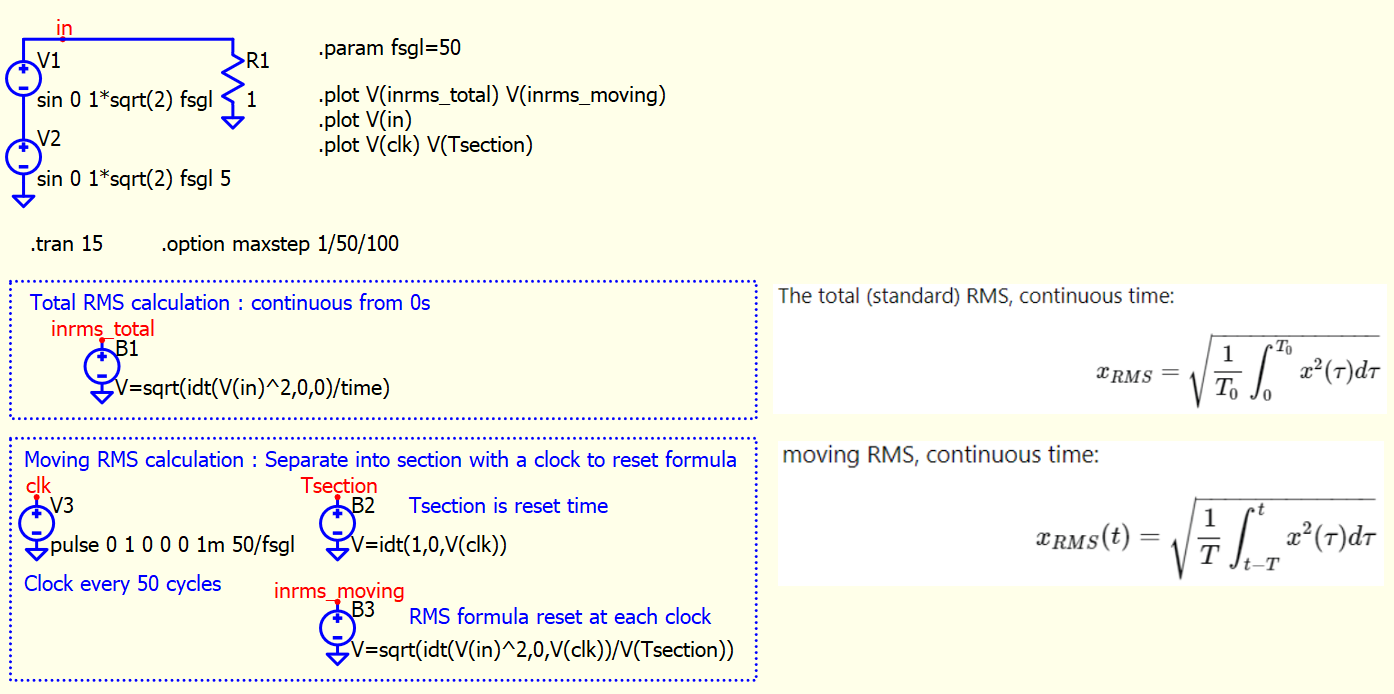
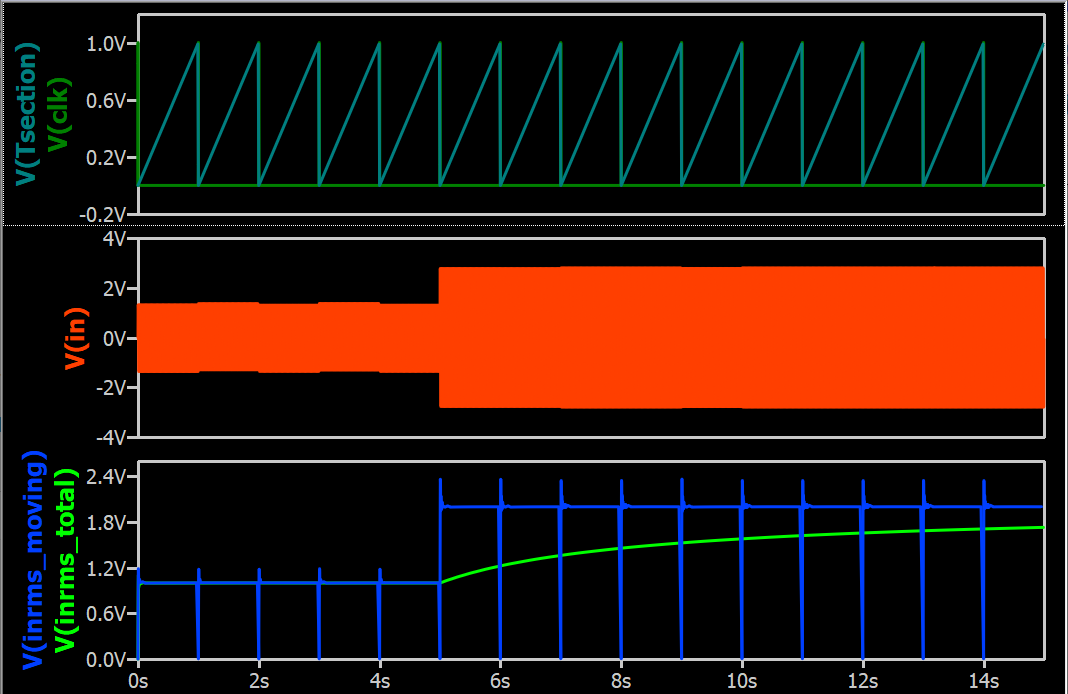
Total RMS is an overall result and can measure in waveform viewer.
If you need a curve of moving RMS, it will require math through the simulation.
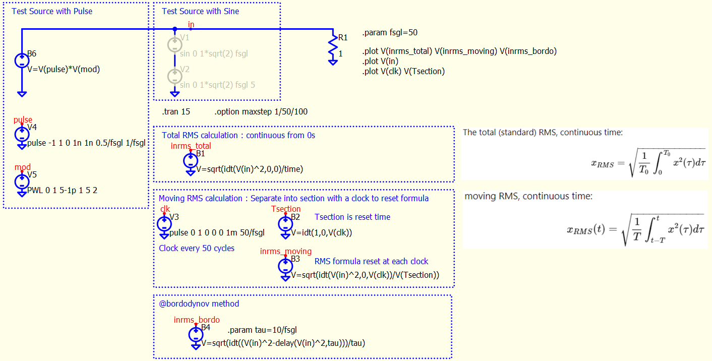
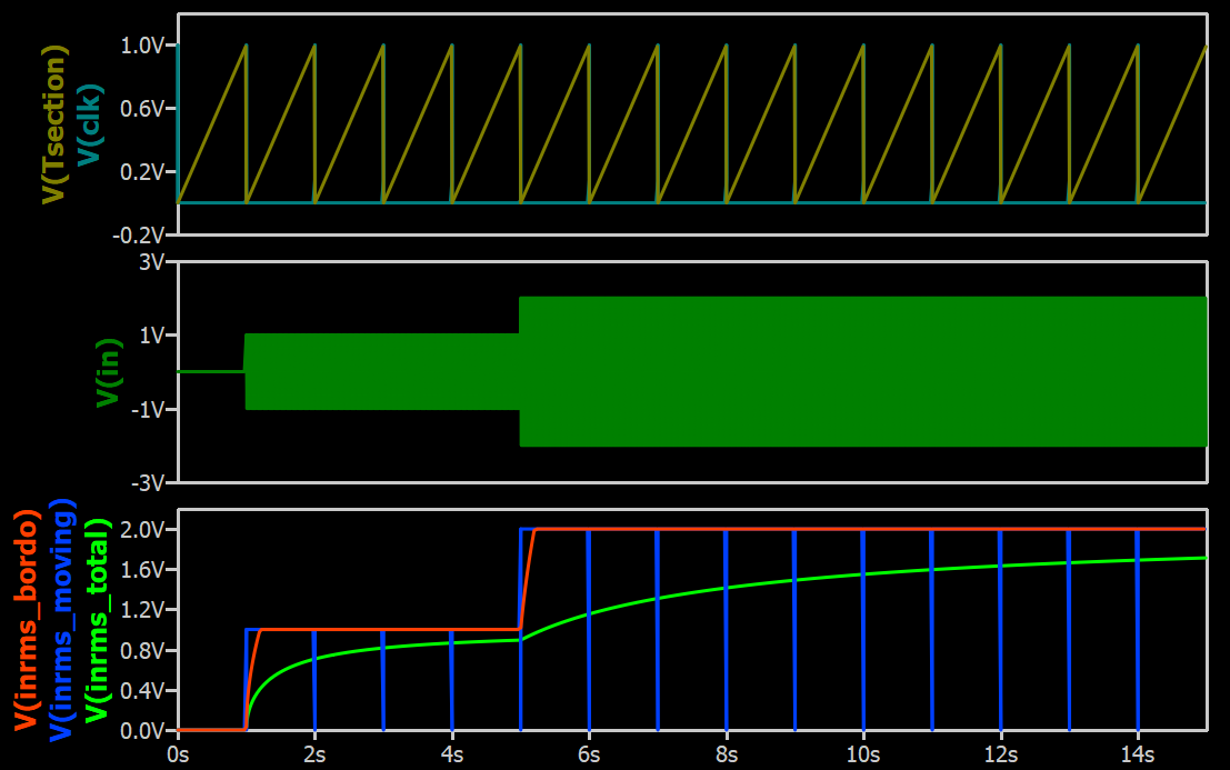
This is an example to implement total rms and moving rms.
- Total RMS : Equation is simple, but if signal level change, as total rms integrate signal from time=0s, you can only get rms over entire time, not the new signal level section rms only.
- Moving RMS : It requires to reset the formula periodically. Every time it reset, calculation has a ringing. A sample and hold can help to remove that, but here just to demonstrate the idea.
Normally, rms is a post processing calculation with .meas or Ctrl-RightClick a signal in waveform viewer, except your circuit need rms for feedback or control purpose.
1 Like
Were can I find the types of documents which shows the key bindings for qspice
2 Likes
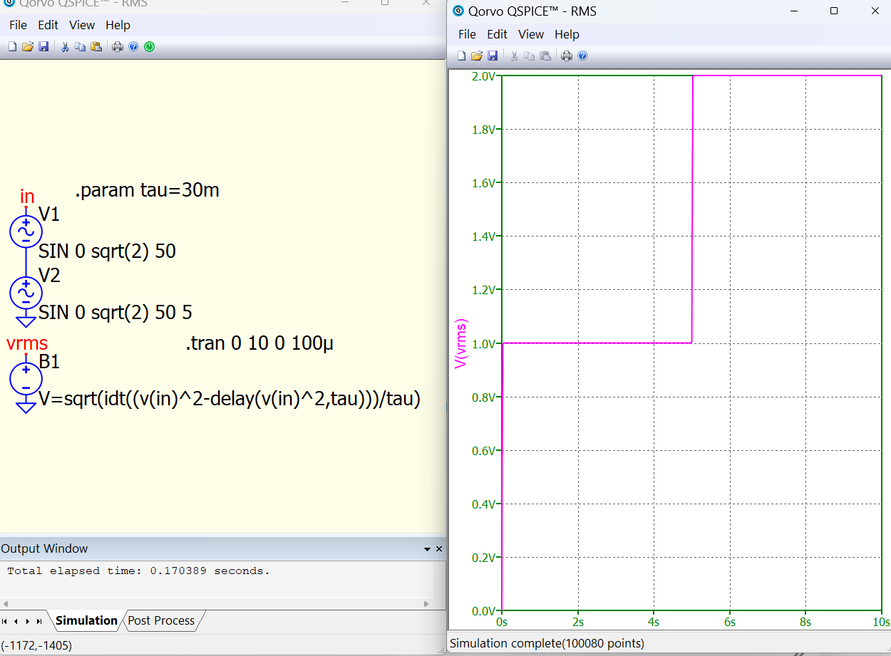
This is a very interesting method, but I cannot get it to work with pulse source.
Am I missing something? Or this method has limitation?
RMS - Total and Moving (Sine and Pulse Test Source).qsch (1.7 MB)
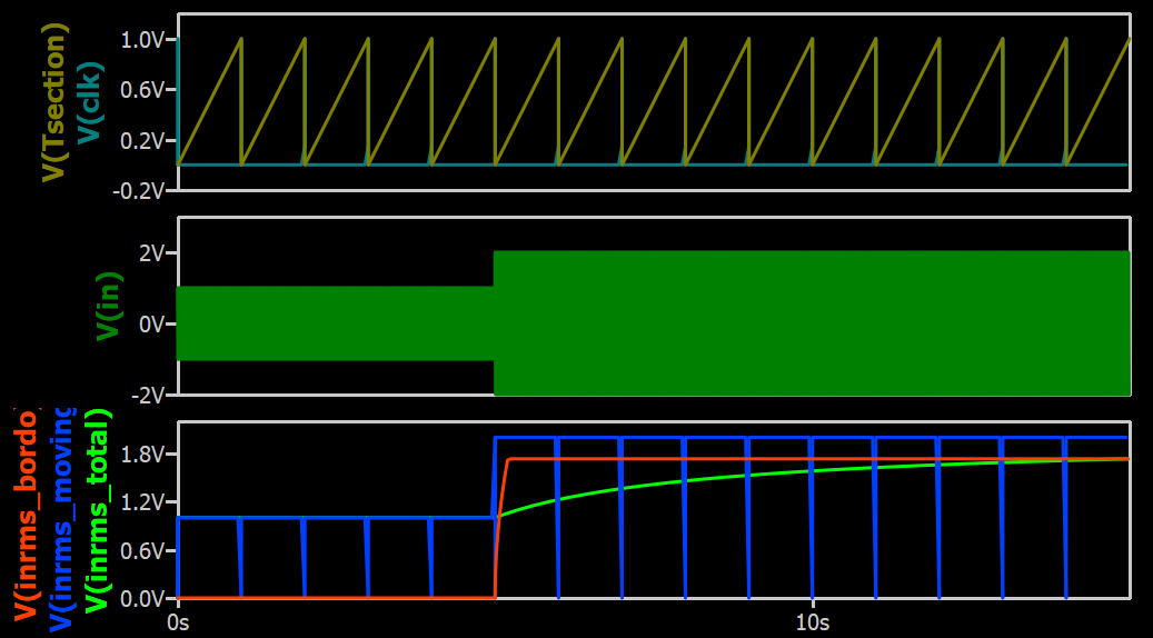
The method you proposed work fine now. The root cause is delay function with pulse.
If I setup a delay to make sure V(in) start with 0V (not 1V or -1V) at 0s, I can get a correct result. Thanks for sharing this method!!
RMS - Total and Moving (Sine and Pulse Test Source).qsch (1.7 MB)
I simulate the behavior of real devices.
You understood everything correctly. The calculation takes place on an interval that slides in time. At the beginning, an error occurs at an interval equal to TAU, and then everything is correct. In fact, this is the inertia of the meter. All meters of both current and voltage have inertia.
1 Like
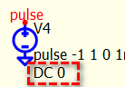
Another solution is to add DC 0 to pulse source. This force pulse source to initial at 0V instead of <value2>. With that, delay function will not start at <value2> and can start from 0V and not to confuse the math.
1 Like
Think about this formula again. As delay function initial value from 0s to tau depends on initial value of V(in). Although Pulse source can force initial value with DC 0, but for other source likes sine, if an offset is defined, initial at 0 is not possible.
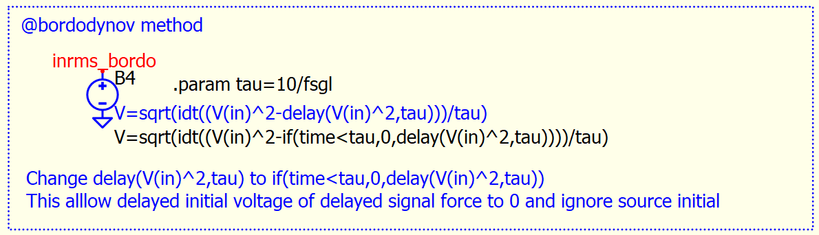
The best is to have formula must set delayed V(in) to 0V between 0s to tau. It can be achieved by adding if condition to the formula.
RMS calculation in B-source, modified from @bordodynov formula
V=sqrt(idt((V(in)^2-if(time<tau,0,delay(V(in)^2,tau))))/tau)
I used this method when analyzing power supplies in LTspice, and I usually add the UIC option in this case and I had no problems.
1 Like
Hi @bordodynov,
I used this method and it works perfectly. But I’m relatively new to this and not able to understand what is actually happening and what Tau is/how Tau is chosen. Could you please elaborate if possible?
Hi GVP.
TAU is the interval for which the calculation is performed. Real analog meters (arrow meters) have an inertia of the order of tens of milliseconds. It is desirable to have a TAU value of at least the period of the measured value.
1 Like
That’s helpful, thank you so much!