I am trying to use a wrapper file to bridge an existing C code into QSPICE. The current goal is to quickly verify that data/signals are correctly passed from a .c file into a CBlock via a wrapper .cpp file.
So far, I can see that data appears to be processed in logs. However, no plot output is shown in QSPICE. 0415.qsch (1.5 KB) dcdc_sils.cpp (1.8 KB)
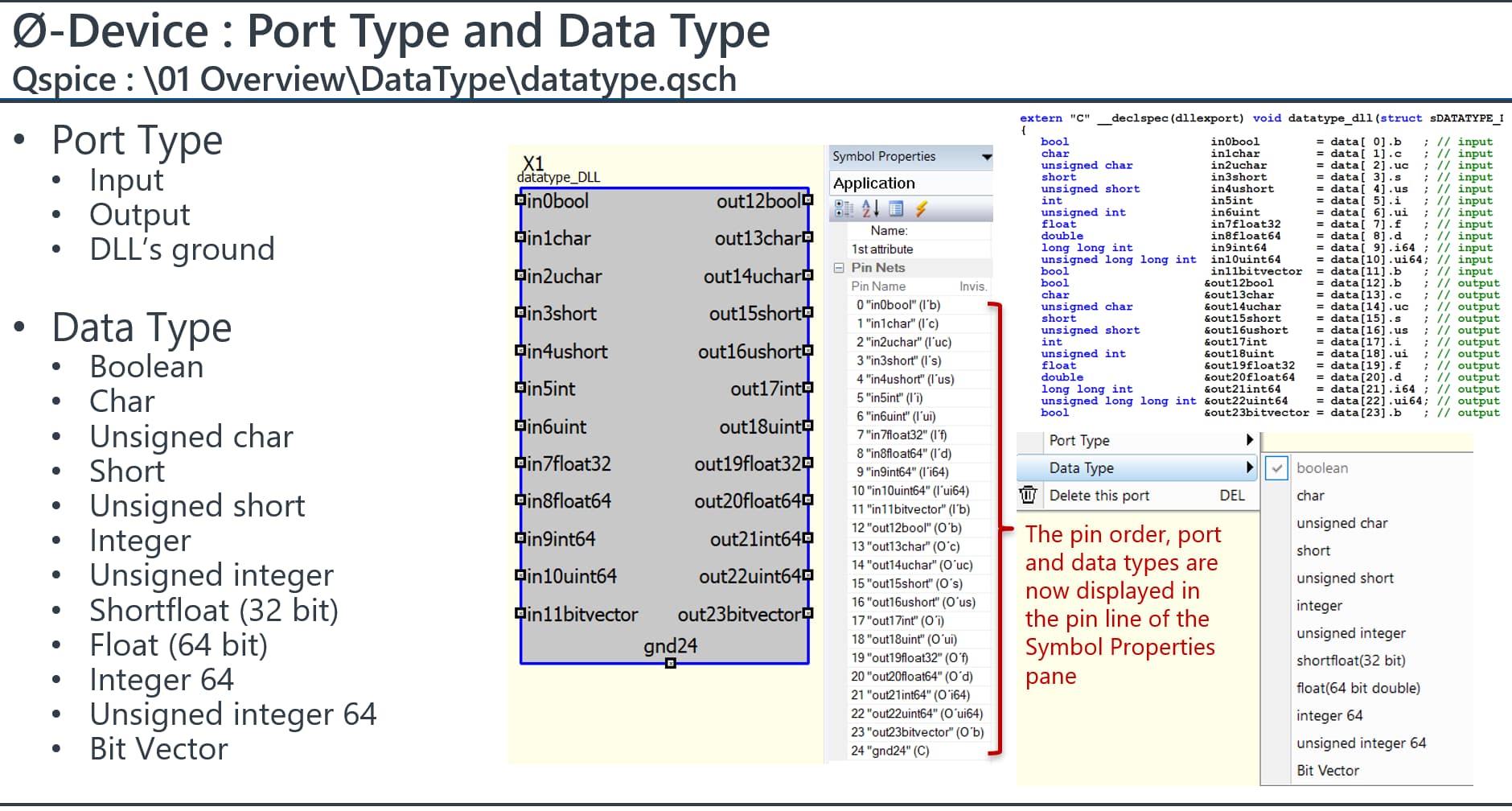
I did generate the C++ file based on the standard template from Qspice, but I modified the pin names afterward. Do yo know where can find the complete pin naming conventions for Qspice?
When I looked at your code, it appeared that the section defining the input and output pins had been deleted.
This is how you create a template. Unless you know exactly what you are doing, do not attempt to modify the code generated by the template.
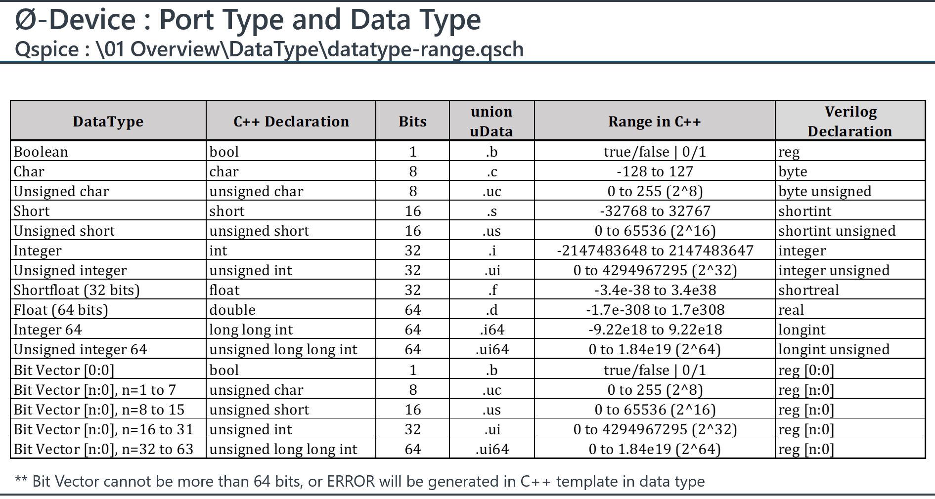
If you add, remove, or modify pins—or if you change their Port or Data type—you must regenerate the template. OR, you can regenerate the port definitions and copy them to replace the existing port definitions in your C++ code.
Well, looks to me like, yes, the code should run and, even though you’re not using the template-generated uData array code, I think that you’re correctly indexing into the array.
When you first run a simulation, the plot window appears but is empty (no traces). Click on schematic pins/nodes to add the traces to the plot window. Or use the .plot directive.
I think pin names must follow standard C variable naming conventions. I don’t think that naming a pin with an array index is a legal name for a variable. (The name of an array variable doesn’t include the index or allocation size.)
Considering what you mentioned about the standard workflow, I’m not sure I fully understand how this should be done in practice.
I’m trying to create a custom symbol in QSPICE and define a large number of pins efficiently.
I considered editing the qsym file directly using a text editor (such as Notepad++) to add pins. However, when I open the qsym or qsch file in the editor, the content appears corrupted .
My new questions here is:
Is it recommended to edit qsym files directly to add multiple pins at once?
From this minimal test, I attempted to bridge data using a non-uData array. I think the output-side data bridging is working correctly. However, on the input side, I still do not have clear evidence of successful bridging, since the values remain unchanged.
I created a summary of Pin Definition in .qsym for DLL symbol, if you plan to directly work on notepad for pin modification.
But again, you should regenerate the port definition after modification of pin.
It is painful to define the port type and data type if you have many pins. I might manually modify those in a text editor, but I never add pins that way because it involves coordinates and other specific information. I prefer to do that in the symbol editor.
Another reason I use text editor is to micro manage coordinates of text, for example, align the text to grid, or modify how far it apart from justification.
For what it’s worth, I’m currently working on a tool to generate symbols for my micro-controller project. The concept is to parse a text file that defines pin name/functionality and produce a *.qsym file.
I think that I have the basics worked out but it will probably be at least a few days before it will be ready to share.
Yes, exactly. For me, editing a text file is much easier—for example, arranging the layout instead of constantly right-clicking. However, it’s still quite tricky, especially when updating pins for the mcu.
Do you create a DLL symbol and then modify it in the symbol window? It is much easier to handle modifications there; for example, you can copy and paste pins and instance parameters, or delete a group of them at once.
For instance, here is a template that includes general data types: bool, int, and double (float64). Creating a DLL block by modifying a template symbol is definitely faster than starting from scratch. DLL-Symbol-BasicPinType.qsym (1.0 KB)
If you frequently work with a specific pin pattern, you can spend time creating a template symbol with the pin names, port types, and data types all pre-defined. This will minimize the work required for your next project.
Can you share what MCU(s) or product line you are targeting?
What I need for my micro-controller project is a bit more complex. In addition to simple input/output pins, I need GPIO/tri-state pins. The GPIO pins require circuitry, essentially a four-pin symbol: One pin connects to the external schematic circuitry. The other three connect to the DLL-side – an input, an output, and a control which sets the state of the tri-state symbol.
So, I want to be able to generate a symbol that has the same number of pins as the MCU. For each GPIO, I need the DLL to have three pins. I need to write the netlist that wires everything up and invokes the DLL. I also want to generate the uData definitions and generate a C++ class to drive the GPIO pins in code. Complicated.
Have you considered how you’re going to handle GPIO pins?
Yes, I’m currently using a similar approach to what you described. However, since I have more than 30 outputs, I prefer editing them in a text editor when generating the symbol, as it’s easier for handling a large number of pins.
For my current task, I’m mainly focusing on validation of digital control algorithms rather than full MCU-level modeling. So at this stage, I’m only using simplified input/output signal mappings to verify control behavior.
I haven’t gone into detailed GPIO handling yet, but it’s something worth considering for future extension