Hi,
I see that default transformer dots in qspice are as below:
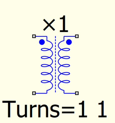
But if I want the dots to be like below how to do?:
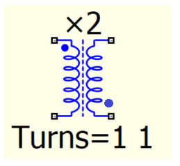
For example:
![]()
Hi,
I see that default transformer dots in qspice are as below:

But if I want the dots to be like below how to do?:

For example:
![]()

Yes, I saw that can be done like you showed. Only I wondering if the actual default qspice transformer can be modified in such a way to have the dot in any of the possible combinations
Another example:
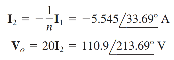
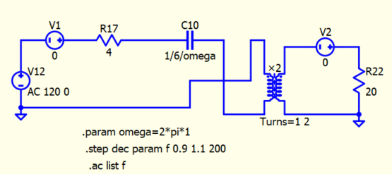
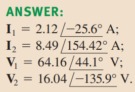
For Vo I think its 360deg-146.31deg=213.69deg.
What I do not understand is why I(V2) not have - sign in front of 5.546 (-5.546) in qspice simulation?
Sorry, Belov, I deleted the post after I realized that you did show swapping the pins. All’s good.
–robert
What’s wrong, RDunn?
Not a comment about what is right or wrong. How do you know the current polarity in the resistors (this is an issue I have always had when comparing spice schematics and simulation waveforms)?
Yes, as the current could enter the dot or leave the dot, thus the current direction through resistor (external component) could be the same or reverse.
This depends on the transformer current ratio(Ipri/Isec=±Nsec/Npri) and voltage ratio(Vpri/Vsec=±Npri/Nsec) vs dots positios, if they are set the correct ones in the transformer model after we change the dots or the voltage at the dots or the current (leaving or entering the dots) of the default qspice transformer. Let’s see If someone can clarify better these things in simulation…
So, why do you think that in qspice simulation the - sign is not present? I tried all the possible variants with the default qspice transformer, but I see only the +5.5467 value, but should be -5.5467:
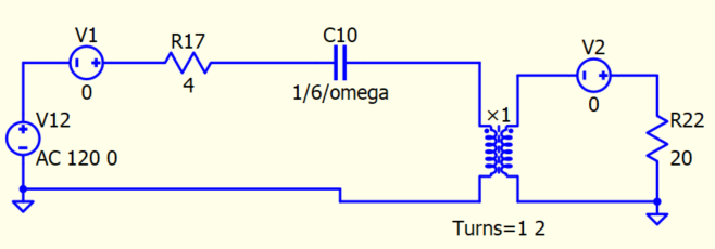
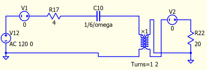
Think about this, how you write -1 in phasor representation? We normally not write in

But write in

Phasor is magnitude and phase format of complex number, people normally not write a negative sign in magnitude.
For the positive current direction of R, C and L, they always defined from node 1 to node 2 (through the device).
SPICE, which originated with netlists (nowadays some people still write in netlists and not using GUI). In Qspice GUI, you can right-click, select “Symbol Properties,” choose the pin name, and highlight which node is which.
In this example, if you probe I(R1), it will give you the positive current flow from node 1 to node 2 based on the definition.
In this example, if you probe I(R1), it will give you the positive current flow from node 1 to node 2 based on the definition.
Well that is convenient if you have Qspice but when you are looking at a document like a PDF or jpeg with a SPICE simulation showing a schematic and a plot of current, there is no reference indicating which way the current is going through resistors, capacitors, and inductors. For circuits like the one Belov posted, how do you know what is going on by only looking at the image? One must assume that the two resistors are placed in the same orientation. My thought is that the schematic should have some way to indicate the direction of current flow.
This is a common situation in SPICE. It is the reason why people often use a 0V voltage source for current measurements. I have also created a current probe symbol specifically for the 0V voltage source. However, by default, Qspice will display a negative value for current when probing a voltage source. To obtain a positive current reading, you need to hold the shift key while probing. You can refer to this post for more information on this topic.
Unable to import Infineon Mosfet Models - QSPICE - Qorvo Tech Forum
Ok, for me is ok, clear at this moment. Thank you all.