Hello guys
I wonder know that how does DWM1000 calculate tag location(x,y value)?
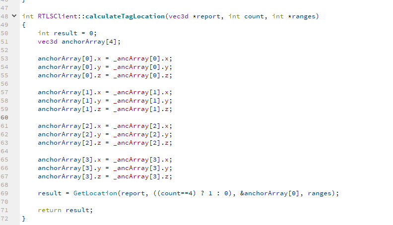
I find these code but it doesn’t make any sense to explain the principle
Hello guys
I wonder know that how does DWM1000 calculate tag location(x,y value)?
I find these code but it doesn’t make any sense to explain the principle
DWM1000 does not calculate “tag location”. DWM1000 is a module which has DW1000 radio. The DW1000 radio can timestamp TX and RX events.
SW/Application controlling the radio, may be bale to workout the range (time-of-flight) between two devices based on their TX/RX timestamps and turnaround times - depending what the application is designed to do.
SW/Application may then use the ranges between number of fixed (in space) devices to work out the location of e.g. a moving device.
Your question does not make sense.
The actual tag location calculation would take place in the GetLocation() function that is called at the end of the code you posted.
If you know the location of 3 anchors and the ranges to those anchors it is simply a mathematical exercise to calculate your location using trilatoration.
If you have 4 ranges then you have a few options: 4 different locations using the 4 possible sets of 3 ranges and take the mean/median one. Pick the 3 anchors with the best geometric diversity (which will in theory give the best result) or use a method like least squares which allows you to find a solution using all the data that minimizes the errors.
Thank you for reply. Maybe i didn’t describe the question clearly. My question is that when we get several distance between tag and different anchors, how does the code calculate the coordination of tag location using GetLocation() function
many thanks for reply. i wonder know more about how does GetLocation() function work, could you tell me more details about it? like how does the code calculate the coordination of tag location
I’m not sure exactly how the decawave implementation does it, I don’t use theirs. I over determine location using up to 8 anchors and ranges and throw all the results into a least squares optimization algorithm to solve for location using an open source library for the actual calculations.
But google trilatoration and you’ll find lots of examples on how to do this, it’s a standard mathematical problem.
Hi
The way TREK calculates location is described in the TREK DecarangeRTLS source code guide, which is available when one downloads the TREK package from our website.
Also note that TREK protocol is limited in what it does and it cannot be changed easily. E.g. tags range to 4 anchors, this is fixed. All anchor addresses are fixed and so adding more nodes needs a good bit of redesign. And I think this is what Andy has done as he has 8 anchors up and running.
And as Andy states there are various trilateration examples on the website, like http://borg.cc.gatech.edu/?destination=node%2F299,, https://github.com/lemmingapex/trilateration and search google for more
Leo
Hi! I am currently adding extra 4 anchors to my project. Anyone have the idea on how to start multilateration code with 8 anchors?
Generally you are going to have to create a more custom system in order to use more measurements. The supplied positioning system code will only range to 4 tags at a time so you have to start to play games to trick it into talking to more. At a certain point it becomes easier to start again rather than try to modify code to do something other than what it was designed for.
Once you have the measurements then as mentioned above there are a number of ways to combine the data.
For reference we went for fully custom firmware and radio protocol that will measure to either 8 or 12 anchors at a rate of 2400 measurements per second. These are filtered and smoothed and then fed into a least squares position and velocity calculation to give 100 Hz positions. This position calculation isn’t fixed to any specific number of anchors and will work with 3 upwards, in theory due to the filtering and smoothing and the way we handle transitioning between anchors we could end up using up to 14 anchors simultaneously however 12 is a more realistic upper limit.
This UWB only position is then fed into a kalman filter than combines it with inertial measurements to give a final position, speed and orientation output.
The end result is this Simulcam demo using VIPS indoor positioning system - YouTube, left is live camera, right is UWB/inertial position fed in real time into unreal running a model of the office.
Hello. Could you please send a link to the program