I have a pretty simple question regarding the MDEK1001 system.
I’ve been concerned with the z-channel accuracy (the xy-accuracy is pretty good). Due to the nature of the setup (1500mm x 1500mm square defined by four tags raised 770mm off the ground - this geometry is a constraint), I know the z-channel is going to be significantly more affected by GDOP than the other two channels, but I’m getting errors of sometimes 2000mm (compared to an indoor motion tracking system), when trying to estimate the position of a tag (mounted on a drone) - keeping in mind this is a COMPLETELY empty room the drone is flying in.
Looking at the pseudo-ranges between the tag and individual anchors, I’m seeing a time-varying bias of up to (+_) 200mm, which I think explains this huge error (I’m also seeing multipath like effects due to this shifting bias). As the documentation states, and somewhat validated in testing, the antenna is omnidirectional (in the xy-plane), and so relative attitude between the tag and anchor is not the source of these pseudorange errors observed.
Is a time-varying bias like this normal, with this magnitude? Is there anyway to correct for this (subtracting the average of this bias from each anchor’s pseudo-range doesn’t really help).
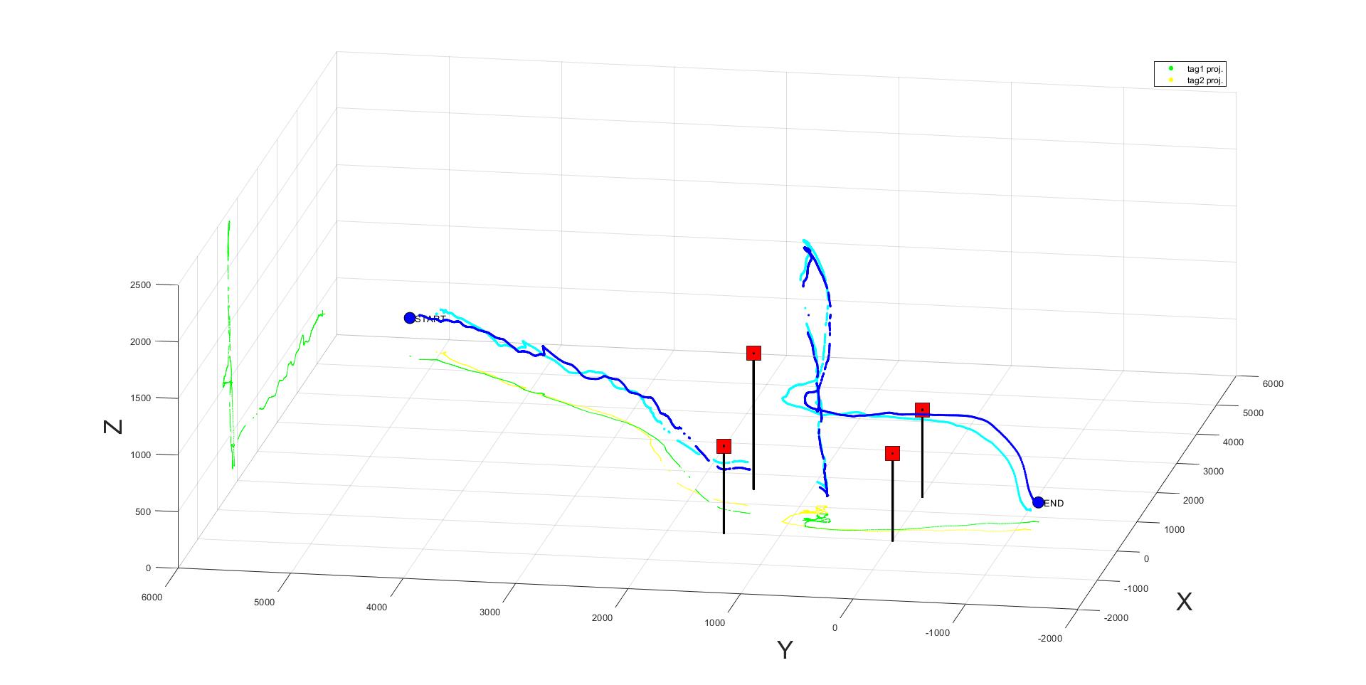
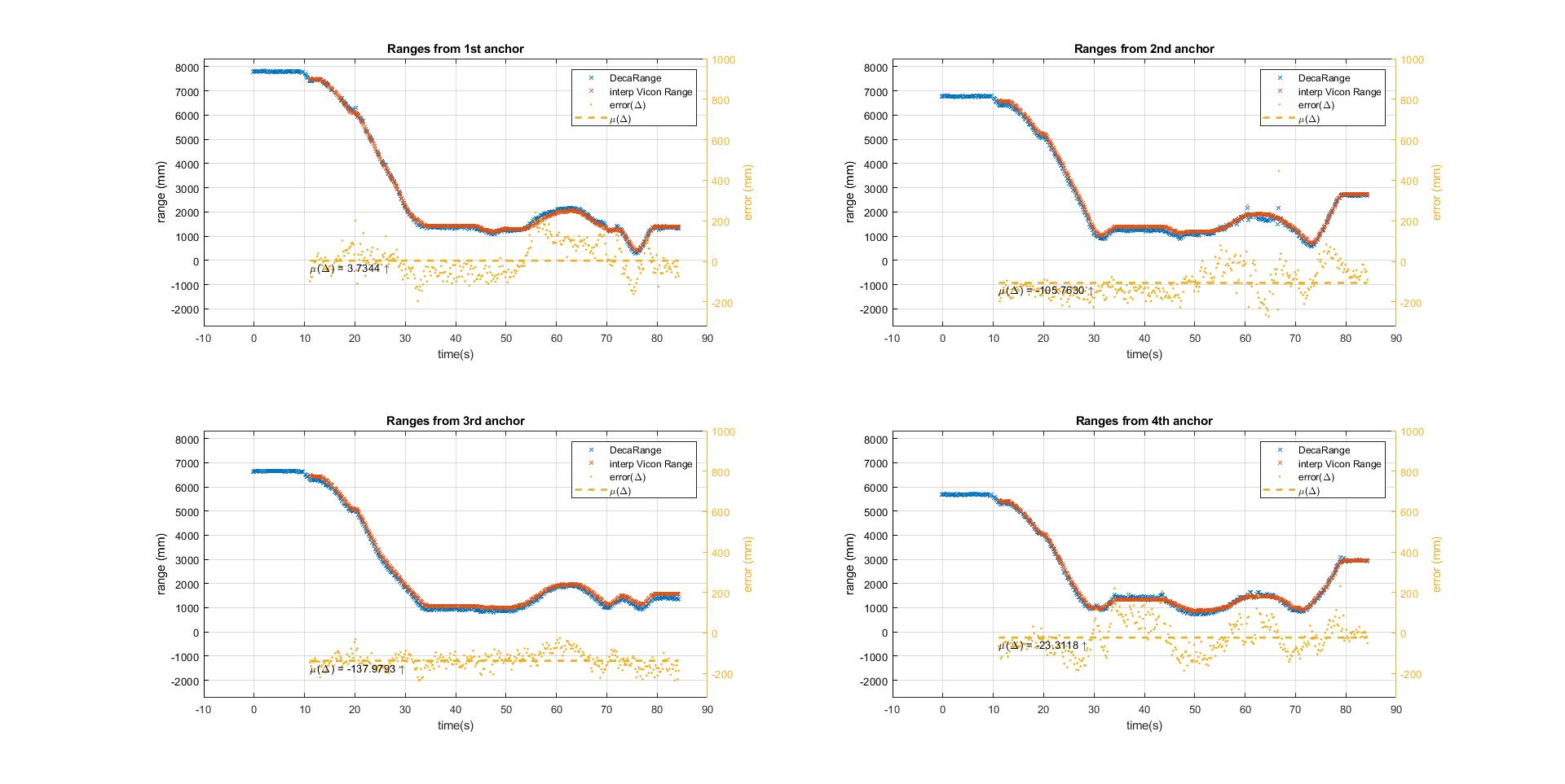
Absolutely, attached I have my MDEK setup (with tag trajectory in dark blue; light blue is second tag not under scrutiny) and also the range measurements from tag to the four anchors, labelled A1, A2, A3, A4. On the range plot you will see, in blue, the decawave range measured from A4 to tag, in red, the Vicon motion tracking data (or truth), and, in yellow, the error between the Deca measured and truth.
As you can see, there is a non-zero mean in the individual range biases (some positive, some negative). They are time varying with no relationship to attitude attitude.
Is the variation due to time or due to relative orientation?
I’ve seen 15-20 cm jumps due to orientation in the past.
Place the two a fixed distance apart and slowly rotate one about the centre of the antenna and see what happens to the range.
This is a function of both the antenna itself and any metal or just about any other material close to the antenna.
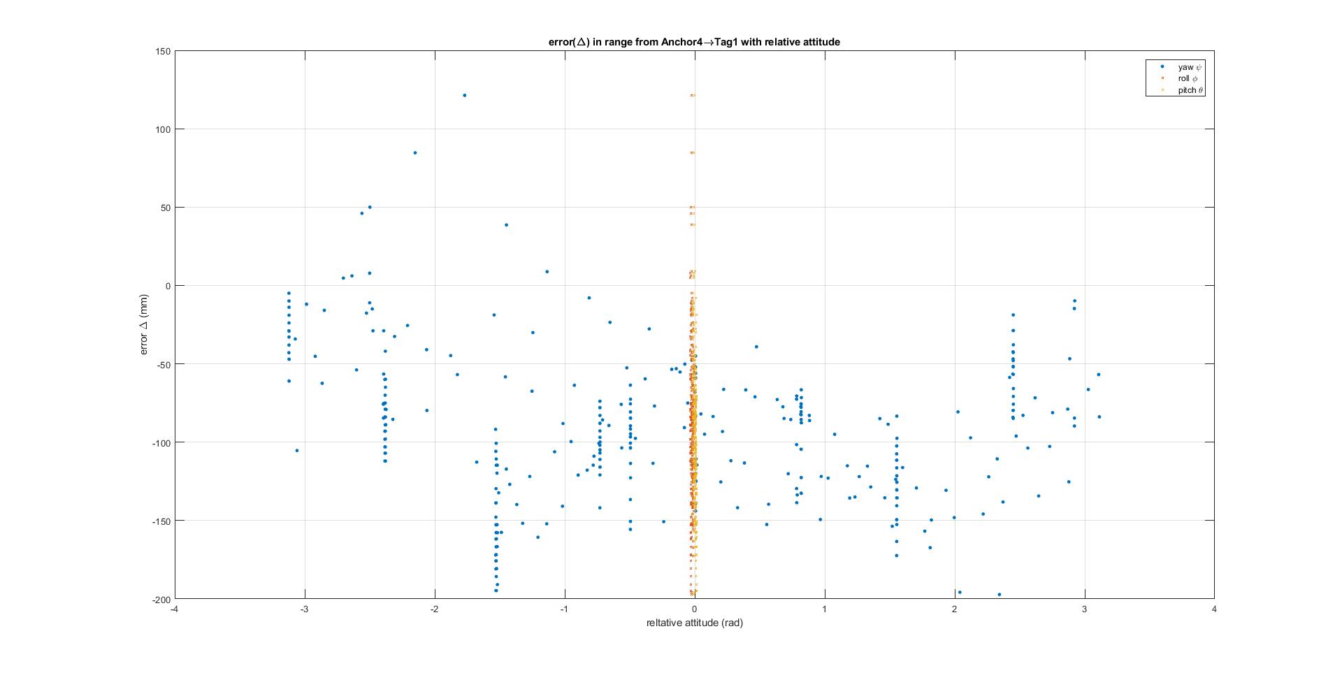
So I thought about the relative orientation being a factor. Both tag and anchor share parallel “z” axis (that is, they are both standing straight up), so only the relative “yaw” angle between the devices varies. I plotted the relative attitude of the tag w.r.t A4 (I realise I didn’t label my anchor devices in the figure above - A1 (0,0,770); A2(0,1500,770); A3(1500,0,770); A4(1500,1500,1200)).
Below is a plot of the range error (mm) between tag and A4 with relative angle (radians), plotting three channels: yaw (about tag’s z-axis (up)), pitch(about tag’s y-axis(right)), roll (about tag’s x-axis(out))).
This experiment consisted of holding the tag within the anchor defined area and rotating it in yaw (rotate 90degrees, hold for a few seconds, rotate 90 again, hold for a few seconds, and repeat for a few revolutions). You can see how wildly this range error varies, and there’s no strong correlation between error and orientation.
Could it be a calibration issue? But calibration only calculates a stationary time bias, doesn’t it, and then subtracts that from each pseudo-range? Even when ranges are small (<1500mm) and device is held stationary, how does the pseudo-range vary so much (by as much as 400mm at times)?
Can you think of any other sources of error which would account for this time-varying bias?
Also, since the antenna has a relatively omnidirectional radiation pattern (in the xy-plane) when the devices are orientated similarly, shouldn’t any errors be independent of relative orientation (I’m basing this statement off the chip-antenna data sheet)?