I have been a user of LTspice for the last 20 years and love that program over the years it has helped me visualize so many issues and design many successful circuits. So I thought I try Qspice and although there are some similarities, I am struggling to get some of my circuits that I have simulated in LTspice to work on this program. I simulated a power supply using a Mazilli flyback circuit many years ago that has worked quite well on LT Spice however I cannot seem to make it work in Qspice any suggestions or hints will be greatly appreciated…Thank you
Sage-ELF-PS.qsch (18.6 KB)
irf640s.txt (1.6 KB)
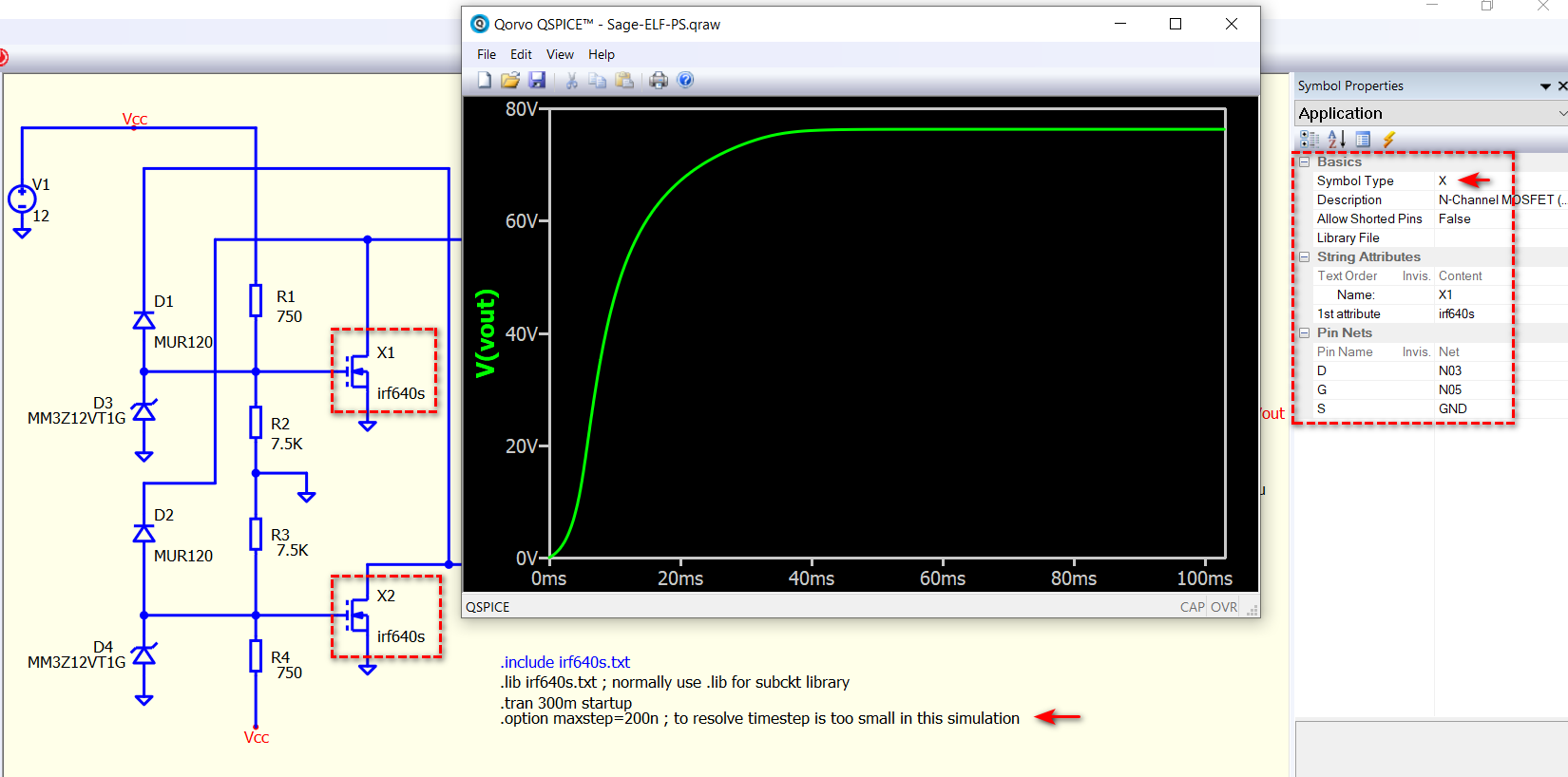
This seems to be a self oscillate gate driving circuit, and I found it run into timestep is too small after I resolve the critical problem.
The critical problem that stop you from running this simulation is the misuse of NMOS symbol. Build-in NMOS should call to use .model. But you call irf640s.txt, which is a subcircuit (.subckt), with that, your symbol type should be X (.subckt) instead of M / MN.
What I do is to replace your MOSFET symbol with a generic subckt symbol. I created a symbol in my symbol library, which is NMOS-Generic.qsym, and my symbol library is in this Github link, or I also attach it below. This is a three-terminal subckt with pin sequence as D, G, S
Qspice/Symbols at main · KSKelvin-Github/Qspice · GitHub
NMOS-Generic.qsym (894 Bytes)
I changed .include to .lib, actually, this is not a necessary change, but normally, I use .lib to call for a subckt library.
If I am correct, Qspice doesn’t support startup in .tran, except there is change that I am not aware.
Finally, with above change, simulation can run but return timestep is too small error at ~5ms. I don’t know why this occur, but a quick solution is to limit maximum timestep in this simulation setup by using .option maxstep. In my test, limiting it to 200ns can eliminate this error, but total simulation time for .tran 300m is about 120s in my laptop.
This is an updated schematic which can work in my test. Normally, Qspice can handle a simulation faster than LTspice. But I am not sure if it does for this one. If anyone can figure why timestep is too small can occur in this simulation without using .option maxstep as solution, possibly this simulation can run much faster.
Sage-ELF-PS.qsch (18.7 KB)
Thank you so much with your help with this. I wasn’t sure whether it was the mosfet model or something to do with the .tran simulation statement timing. Again, I am finding that moving from LTspice to this version is not all that intuitive and I should have known that my subckt should have been X instead of M which is the same case on LTspice. After running the same simulation on both LTspice and Qspice I am getting very different resonant frequencies and waveforms between the LTspice and Qspice simulations actually the LTspice simulation is much closer to the real world results I get on the actual hardware. This maxilli circuit should be resonant ~75KHz on Qspice it is resonant at ~22 KHz?? Another thing I cannot figure out is how do change an inductor resistance value? is it through a statement? as there is no longer a dialog box to change these parameters.
Right click on Inductor > Add New Attribute > Type “RSER=xxx”
Parameter add this way is called Instance Parameters. You can go to Qspice help, search for corresponding device, and check what Instance Parameters are available.
Qspice doesn’t have dialog box, initially, I found it quite difficult as I came from LTspice. But just few weeks, I hate going back LTspice, as I enjoy how fast and easy I can build my schematic in Qspice. But not everyone feel this same way.
By the way, I created several guideline, which was initially for my personal note but ultimately shared to community. You can find examples of using different instance parameter for inductor in Device guideline in there.
Once again thank you for all your help and BTW, the previous complaint I had with a resonant frequency being different between LTspice and Qspice was my error as I had left out an inductor on the Qspice simulation so it was my own dumb mistake. But while I am on the subject of frequency, I noticed that when I do an FFT and request for the grid to be shown on the log X-axis I only get the small log ticks but I cannot seem to get a nice log plot that has the full vertical log tick like a get on LTspice, I did some searching on this topic and it appears that this Qspice version will not show that type of log plot?
Oh, yes, there are no minor tick lines in the grid. Perhaps one day we will have this feature.
Just curious, after you fixed that inductor mistake, does this simulation still need a maxstep to get it work without minimum timestep error?
Yes it does. If I comment out .option maxstep= 200n I get the dreaded error: “Timestep too small” so even though I was missing a circuit element there is a definite issue with the time step being too small something like 4.2E-16 at T=0.