Hello, good evening. Im simulating a solenoid to get high voltage. I have a R1=4\Ohm, a L=6mH, and a battery of 12 V.
For some reason I cant see in circuit, the voltage after the the switch open must be 18kv. Im getting Mega Volts.
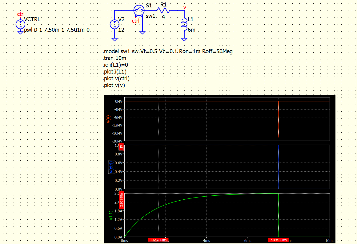
$\tau=1.5m$ and $5 \tau=7.5m$ The key opens approx $1 \mu s$
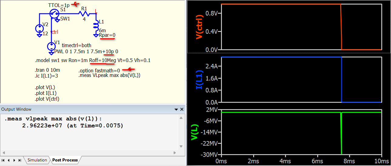
This is the theory behind what you have. To be precise, the simulation must be set up in a way that everything is very precise at the moment of switching. The values of Roff and Rpar of the inductors can determine what you get at the moment of switching off.
In this example, I set Rpar=0 for an infinite parallel resistance of L1 to eliminate this factor, and with Roff set at 10Meg. In theory, the steady-state current I(L1) is 3A. When the switch is turned off, the inductor current cannot stop immediately; this 3A has to flow through R1 and Roff. So, V(L) at ~ I(L1) * (R1+Roff), and in this case, it is approximately 30MV. If Roff is set to 50Meg, theoretically, the voltage peaks up to around 150MV.
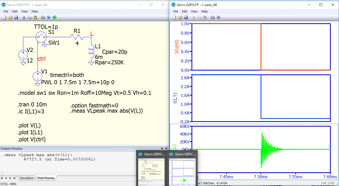
Your actual circuit does not show this (18kV?), as the high voltage when the relay is off is possibly discharge through arcing.
Next time, upload your schematic to save time in reviewing.
L-open.qsch (4.5 KB)
1 Like
Hello @bordodynov and @KSKelvin. Thank you very much for feedback.
Let me introduce the data from the problem. Its also in sadikus book.
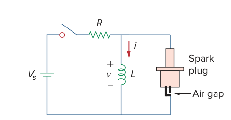
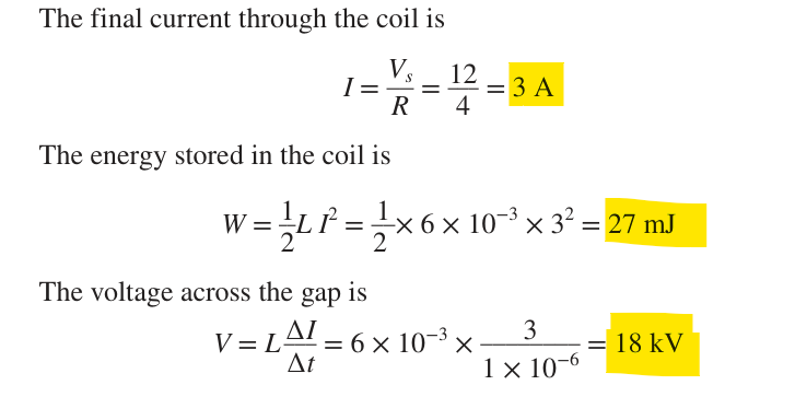
A solenoid with resistance 4 Ω and inductance 6 mH is used in an auto-
mobile ignition circuit similar to that in Fig. 7.78. If the battery supplies
12 V, determine: the final current through the solenoid when the switch
is closed, the energy stored in the coil, and the voltage across the air gap,
assuming that the switch takes 1 μs to open.
As we can see, the theory says the voltage peak is 18KV. Thats interesting as its not so simple to modeling a simulation and we take care with some details. I did other tryes and got 20 KV peak to peak. Maybe my model isn`t correct.
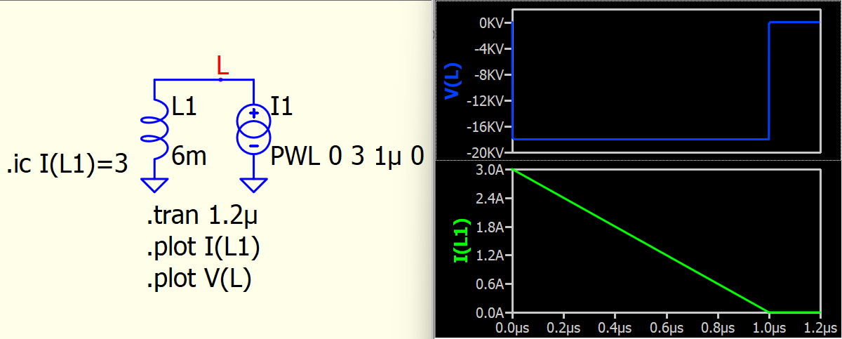
This book made a fundamental mistake by assuming that the switch takes 1 μs to open and can act like a constant slope current source.
It is true that if the current draw from the inductor can be controlled through a constant slope current source with 3A/μs, the voltage across the inductor is 18 kV. (refer to the simulation attached)
The author assumes the switch takes 1 μs to open, so he assumes that within this 1 μs, the current can linearly drop from 3A to 0A and uses the inductor formula to suggest that the voltage is 18 kV. But do you think the switch can function as such a current source?
Just don’t trust every article and book; make judgments yourself.
Inductor-IPWL.qsch (1.7 KB)
Hello. Thanks. I currently don’t have a level to see this tricks and suspect from sadiku, but got many simple erratas in this book.
I’ll take care with that.