Hi all,
Does anyone know if such a symbol exists?
Or maybe do you know if the schematic behind the original symbol is available (for an attempt to implement it if it doesn’t already exist)?
Hi all,
Does anyone know if such a symbol exists?
Or maybe do you know if the schematic behind the original symbol is available (for an attempt to implement it if it doesn’t already exist)?
I guess you didn’t download my entire Symbol library. ![]()
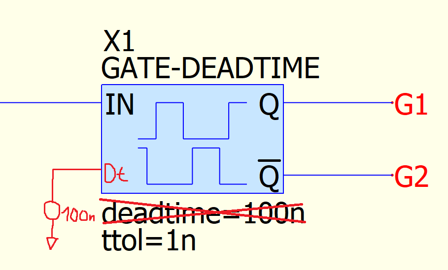
Gate-Deadtime-ctrl.qsym is in the same subfolder of this fixed Gate-Deadtime.qsym.
Hi @KSKelvin ,
Thanks for your answer.
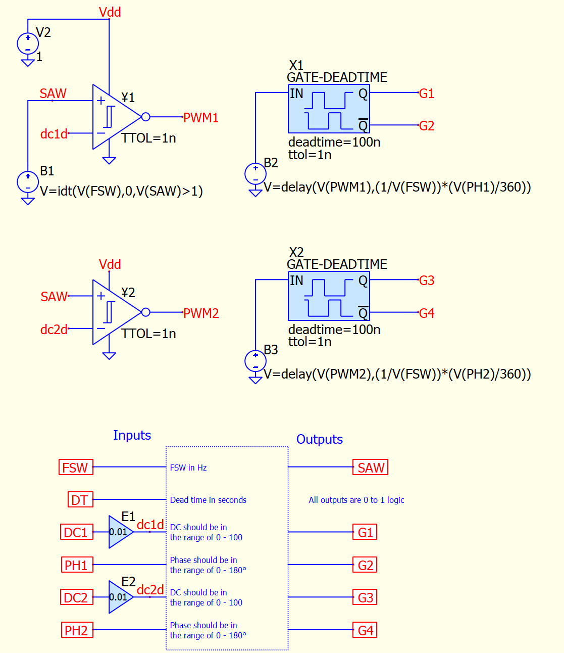
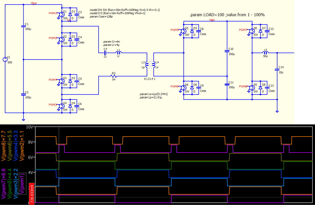
Actually I do have your entire library and I highly appreciate your efforts you have put to build this library. However, this symbol you are suggesting is not for Half-bridge configurations. So, that is why I was wondering if a version of the HB symbol existed and I have missed it. I have seen professor’s’ Alonso LTspice implementation but he uses RC tau which needs also to be “hardcoded”. In the following screenshot you can see what I want to implement and why I need adjustable dead time.
Phase-shift modulation example with adjustable dead time. If possible, avoid using the delay function (analog signal delay) for phase shift control. This approach is impractical in real life, consumes memory and limits your maximum step size in simulation.
By the way, please update Gate-DeadTime-Ctrl.qsym from my Github, I just found that I forgot add TTOL instance parameter.
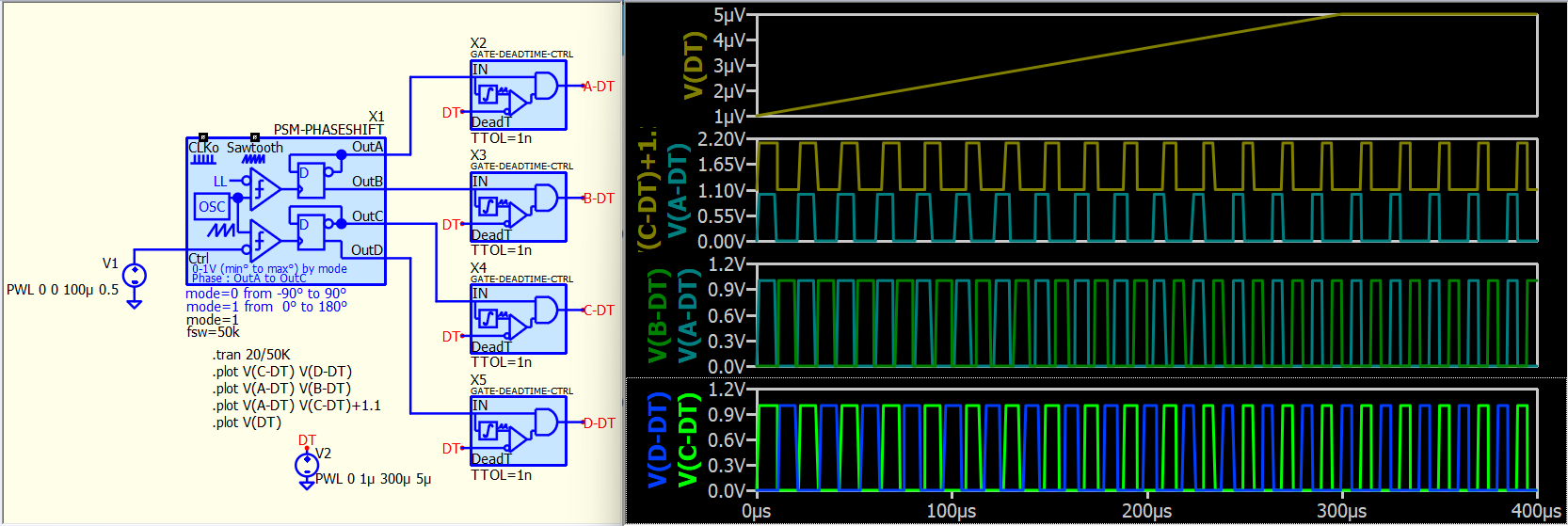
example.PSM.Gate-DeadTime-Ctrl.qsch (18.9 KB)
Thanks for your suggestions. I can do the phase shift with some D-flops etc. and avoid the delay function.
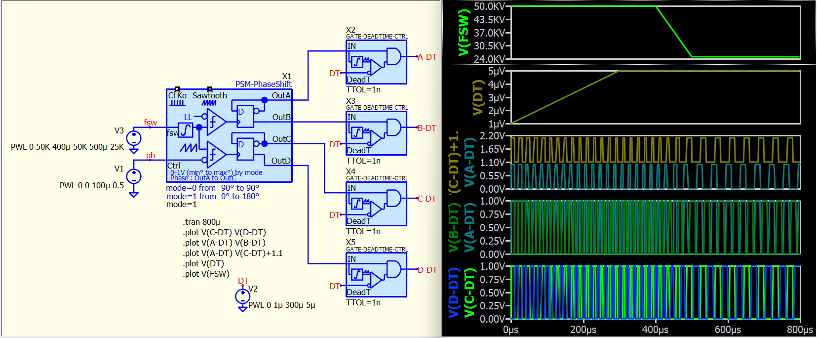
The solution you have just posted is now missing the dynamic change of FSW. In my case, I want to make a PWM modulator for SMPS applications where I need to dynamically change the FSW, duty cycle, dead time and phase shift during simulation. I have done it in a C-block but I would like to do it in circuit as well.
Well… just modify the symbol to allow an external switching frequency setpoint. I prefer the dead time as an external block, and these two symbols can have adjustable switching frequency, phase setpoint, and dead time.
I am uncertain about the role of duty cycle plus dead time in a full-bridge phase-shift configuration. The high and low sides are symmetric in a half/full bridge setup. If you adjust the duty cycle to less than 50%, you essentially introduce dead time. Similarly, adjusting the dead time is equivalent to adjusting the duty cycle in such a system.
To be fair, I cannot guarantee the robustness of such a complex dynamic system. Could you please explain the benefits of having all these parameters to be adjustable during operation?
That solution I think could work for me, I have to give it a try.
The role of such a modulator I am trying to implement finds its use in some resonant bidirectional DC/DC converters with cascaded structures and synchronous rectification. My idea is to use multiple instances of this modulator with different settings. Some of the switches running at double the FSW and some have variable dead time, phase shift and duty cycle. You can see some example waveforms of such a structure which I acquired using the C-block I already have.